background image


18 


Mechanical Installation 


Respect all local standards and requirements during mechanical installation. 

5.1 


Transport 

All devices are installed inside the MV Station before delivery. The MV Station  should be 
transported as a whole. Transport the MV Station by a crane with sufficient load capacity. 

The MV Station is delivered to the user by the forwarding company. After unloading, the MV 
Station will be transported to the installation site by the plant staff. 


Local  standards  and  regulations  on  the  transport  and  loading  &  unloading  of  the 
container, especially those safety instructions, should be observed at all times. 


All the accessory appliances used during transport should be maintained beforehand. 


The MV Station must be transported by qualified personnel. Qualified personnel are 
those who have relevant training experience, especially safety-related experience. 


Keep in mind the dimensions and total weight of the MV Station at all times! 

Ensure that the following requirements are met: 


All the doors are locked. 


Choose the appropriate crane or hoist to transport the MV Station. The crane or hoist 
must be sufficiently capable of bearing the MV Station weight. 


An additional traction vehicle may be required when the road has a gradient. 


Anything, which may hinder the transport, like trees, cables (or the like), should be 
removed. 


If possible, transport the MV Station on fine weather days. 


Warning signs or barriers must be posted near the transport areas to avoid accidental 
injuries. 

Содержание MVS6250

Страница 1: ...MVS6250_6800 SEN Ver11 202003 MVS6250 MVS6800 MV Station Transportation and Installation Guide ...

Страница 2: ......

Страница 3: ...t Protection 5 2 3 Live Line Measurement 5 2 4 Measuring Instrument 5 2 5 Voltage free Operations 6 2 6 ESD Protection 6 2 7 Symbols on the Device Body 6 2 8 Safety Warning Signs 6 2 9 Daily Operation and Maintenance 7 2 10 Others 7 2 10 1 Manual Storage 7 2 10 2 Disposal of Waste 8 2 10 3 Manual Description 8 3 Product Description 9 3 1 System Overview 9 3 2 External Design 9 ...

Страница 4: ...the MV Station 17 5 Mechanical Installation 18 5 1 Transport 18 5 2 Hoisting the MV Station 19 5 2 1 Safety Precautions 19 5 2 2 Hoisting 20 5 2 3 Fastening of Connectors 21 5 3 Foundation 22 5 3 1 Selection of Installation Site 22 5 3 2 Foundation Requirements 22 5 3 3 Recommended Foundation Construction Plan 23 5 3 4 Other Precautions 25 5 4 Securing the MV Station optional 25 5 5 Removing Seali...

Страница 5: ...Cable Connection 37 6 3 5 Auxiliary Power Supply Cable Connection 37 6 4 Checking after Electrical Connection 38 7 Checking before Power On and Power Off 40 7 1 MV Station Container 40 7 2 MV Switchgear 40 7 3 MV Transformer 41 7 4 LV Cabinet 43 8 Troubleshooting 44 9 Routine Maintenance 46 9 1 Safety Instructions 46 9 1 1 Safety Rules 47 9 2 Maintenance 47 9 2 1 Introduction 47 9 2 2 Maintenance ...

Страница 6: ... 52 10 1 1 Five Safety Rules 53 10 2 Maintenance 53 10 2 1 Introduction 53 10 2 2 Maintenance Interval 53 10 3 Maintenance Items 54 11 Parameters 56 11 1 Technical Parameter 56 11 2 Tightening Torques 57 12 Contact Information 58 ...

Страница 7: ... the construction and working principle of the PV grid connected power generation system and familiar with the construction and working principle of the MV Station upstream and downstream equipment Trained especially in the installation of electrical devices Capable of coping with the dangerous and emergency situations during the installation and commissioning Familiar with the country regional st...

Страница 8: ...injury NOTICE indicates a situation which if not avoided could result in equipment or property damage NOTE indicates additional information emphasized contents or tips to help you solve problems or save time The symbols below may be pasted on the electrical parts of the MV Station or its internal device Make sure to read the following symbols and fully understand them before installing the equipme...

Страница 9: ... This Manual 3 1 4 Terminology Name For short MV Station MV Station COM100 Communication Box COM100 communication Box The foregoing devices are expressed in the abbreviation form in this document unless otherwise specified ...

Страница 10: ...on the grid connection Lethal voltages are present inside the device Pay attention to and follow the warning signs on the device Respect all safety instructions in this manual and other pertinent documents Electric shock or fire may occur due to device damage or system fault Visually inspect the MV Station for device damages or other hazards Check if the external devices and circuit connections ar...

Страница 11: ... voltages are present inside the device Death can result from burning and electric shock due to touching the live components of the MV Station During live line measurement use suitable protective equipment for example dielectric gloves and accompanied by other persons 2 4 Measuring Instrument The instrument for measuring the electrical parameters should meet the following requirements The instrume...

Страница 12: ...ompletely voltage free 2 6 ESD Protection Devices may be damaged irreversibly by electrostatic discharge ESD Avoid unnecessary touching of the PCB Observe all the ESD related safety instructions Wear proper personal protective equipment PPE such as wrist strap 2 7 Symbols on the Device Body Symbols on the device contain important information on safe operations of the MV Station and its internal de...

Страница 13: ...deration during daily operation and maintenance The nameplate is pasted on the MV Station body It contains important parameter information of the devices Protect the nameplate during all operations Wear proper PPE such as safety glasses safety footwear and safety gloves if necessary All necessary auxiliary measures are advisable to ensure personal and device safety 2 10 Others 2 10 1 Manual Storag...

Страница 14: ...nvenience there are a large number of pictures in this manual These pictures are indicative only For details about the device please refer to the actual product you receive Keep this manual at a convenient place near the device for future reference All the descriptions in this manual are for the standard MV Station Please inform us in the purchase order if you have specific requirements The actual...

Страница 15: ...e PV power generation system with the MV Station is shown in the following figure PV Array PV Array Combiner Box DC AC Communication Grid MV Station Inverter Remote Monitoring Inverter 3 2 External Design 3 2 1 Composition The MV Station consists of a transformer room and a switchgear room as shown in the figure below 1 2 No Name Description 1 Transformer room Including one MV transformer and an L...

Страница 16: ...on from the grid 3 2 2 MV Station Views View Description Front view Front of the MV Station A Back view Back of the MV Station Left view Left of the MV Station Right view Right side of the MV Station Figures are indicative only and actual product may differ Installation Area of Fire Extinguisher optional Figure A above shows the installation area of the fire extinguisher On site fire extinguishers...

Страница 17: ... Width W Height H Depth D Width W Height H Depth D 6 058 mm 2 896 mm 2 438 mm Clearance Requirements 8219 5349 3 3 Internal Design 3 3 1 Internal Composition Device layout inside the MV station is as follows A B D C No Name A LV connection area B MV Transformer C MV switchgear ...

Страница 18: ...580 1040 D 200 200 3x Table 3 1 Cable entry of MV Station No Name Description A LV side cable entry All LV side cables connecting the MV transformer go inside through this entry B Maintenance entry This entry is designed for future cleaning and oil tray maintenance C Communication and power distribution cables entry All communication and power distribution cables connecting external device go insi...

Страница 19: ...ing figure 4 3 3 3 Internal Devices The MV Station consists of the MV transformer MV switchgear communication box and control panel MV Transformer Figure Name Description 20 40 60 80 100 120 Oil temperature Indicator The alarm temperature is set to 90 C When the oil temperature reaches the value alarm signals will be sent to the communication unit The tripping temperature is set to 100 C When the ...

Страница 20: ...lief valve MIN 30 C MAX Oil level indicator The MV transformer will stop operating if the oil level falls below the lowest scale on the oil level indicator or below the oil level scale required for safe operation of the transformer When the oil level is excessively high open the drain valve to lower the oil level When the oil level is excessively low disconnect the transformer and check the oil ta...

Страница 21: ...alarm signal contact will be connected and alarm signal will be sent out In case the gas generated is heavy the tripping signal contact will be connected and the circuit breaker in the switchgear trips so that the transformer will be disconnected from the grid to avoid device damage Note is optional Note Parameters marked with a and b are factory default values and can be adjusted according to act...

Страница 22: ...or inside devices may be damaged during transport Therefore once you receive the MV Station a detailed inspection is necessary If any damage is detected contact the forwarding company or Sungrow immediately Examine the contents of the shipment to check the scope of delivery described in the packing list for completeness Check to make sure the MV Station and inner devices are of the same models as ...

Страница 23: ...heat the MV Station internal devices Temperature 35 C 70 C Relative humidity 0 to 95 and non condensation Store the MV Station on a dry clean and solid ground with sufficient load bearing capacity The ground should be flat without water bumps or plantings Lock the MV Station internal devices and the MV Station during storage Take proper protective method to prevent the water and dust penetrating i...

Страница 24: ...pliances used during transport should be maintained beforehand The MV Station must be transported by qualified personnel Qualified personnel are those who have relevant training experience especially safety related experience Keep in mind the dimensions and total weight of the MV Station at all times Ensure that the following requirements are met All the doors are locked Choose the appropriate cra...

Страница 25: ...be stopped on violent weather days For example in strong wind heavy rain or thick fog conditions Please observe the following items All safety requirements must be met A professional instructor is required in the whole hoisting process All the used slings must have the load bearing capacity of at least 30t The crane should have sufficient arm length and radius of gyration All the connection point ...

Страница 26: ...hen the MV Station has been hoisted for about 300mm away from the ground stop to check if all the connections are still firm After confirmation continue hoisting the MV Station When transported to the final location the MV Station should be put down slowly and steadily The final location should be firm level and well drained The MV Station is supported by four bottom fittings on the ground The MV ...

Страница 27: ...ig 5 2 Hoisting from top fittings Item Requirement Steel Length L 6 5 m Steel Rope Qty 4 pieces 5 2 3 Fastening of Connectors Use slings with hooks or U hooks to hoist the MV Station The lifting devices should be correctly connected to the MV Station ...

Страница 28: ...ient and geological conditions such as stress wave emissions the level of underground water table and etc should be taken into account The ambient environment should be dry well ventilated and far away from inflammable materials The ground at the installation site must be compacted enough Relative compaction of the ground should be equal to or greater than 98 Otherwise take proper methods to stren...

Страница 29: ...g to local soil conditions Cable route should be taken into account According to the cable design of MV Station and for easy electrical connection please establish cable trenches on the bottom of the MV Station i e reserve the cable trenches inside the foundation and pre bury the wire pipes The dirt dug out should be cleared immediately 5 3 3 Recommended Foundation Construction Plan The following ...

Страница 30: ... No Name A Foundation B Solid ground e g gravel Foundation 2344 2088 5 2088 5 1700 C No Name C Pre embedded 20 channel steel The foundation plan described in this chapter is for reference only Consult the professional personnel before construction ...

Страница 31: ... shape angle steel is reserved at the bottom of the container A A A A The number of L shape angle steel shown in the figure above is for reference only and it can be adjusted according to onsite conditions Preparing Installation Tools The following tools may be used in installing the L shape angle steel No Name Resource 1 Marker Beyond the scope of delivery 2 φ22 percussion drill Beyond the scope ...

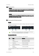
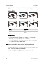
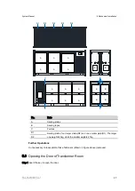
Страница 32: ...lation site to prevent the MV Station from being immersed in water during heavy rainfalls Do not plant any trees near the MV Station installation site to prevent the damage of the MV Station caused by tree leaves or stems 5 5 Removing Sealing Plates Sealing Tapes and Fasteners The sealing plates sealing tape and fastens are attached to the enclosure of the MV Station to prevent moisture penetratio...

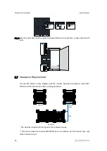
Страница 33: ...s B Sealing tapes C Fastens D1 Sealing plates four larger plates D2 and one smaller plate D1 The larger one weights 43kg while the smaller weights 21kg D2 Further Operations It unnecessary to reassemble these fasteners shown in figure above removed 5 6 Opening the Door of Transformer Room Step 1 Insert the key to open the door ...

Страница 34: ...rance Requirement On site MV Station works together with the inverter Required clearances around MV Station and the inverter are shown in the figure below 2344 2000 MV Station Inverter Inverter The distance illustrated in this figure is the minimum values This manual takes the inverter SG3125HV 20 as an example and the inverter type may differ in actual project ...

Страница 35: ...e voltage free before may contain lethal voltage Accidental touch may cause serious damage Make sure there is no system ground fault before operation and take proper protective measures Observe all the country specific standards and regulations Connect the MV Station to public grid only after receiving authorization from the local network operator Only professional electricians can perform the ope...

Страница 36: ...as the communication cable please follow the related requirements of the fiber manufacturer about the min allowable bending radius Only professional electricians can perform the electrical connection Professional electricians should meet the related requirements listed in 2 Safety Instructions in this manual Sungrow should hold no liability for any personal injury or property loss caused by ignora...

Страница 37: ...gnal interference 6 1 2 Five Safety Rules During electrical connections and other operations on the inside device observe the following Five Safety Rules Disconnect all the external connections and disconnect the MV Station internal power supply Avoid any inadvertent re connections Verify that no voltage or current is present with appropriate testing devices Ground and short circuit whenever neces...

Страница 38: ... phase and each phase supports 400 mm2 copper aluminum wire utmost B Connect to MV grid Depends on the switchgear type Specifically refer to the corresponding manual C Auxiliary power supply port D Ethernet port E Control panel F COM100 Communication box G MV Transformer H MV Switchgear 6 3 Cable Connection External cable connections of the MV Station include grounding cable connection cable conne...

Страница 39: ...according to actual conditions Illustrations Description 60 M10 100 Left side view of the MV Station The external grounding point is shown in the left figure 60 M10 100 Right side view of the MV Station The external grounding point is shown in the left figure Note unit mm The external grounding points of the MV Station can be grounded in the following two manners Connect the grounding cable to the...

Страница 40: ...d connection Perform the external grounding according to on site situation and instructions of the plant staff The grounding resistance should be no more than 4Ω The grounding resistance should be determined according to local standards and regulations The country specific regulations and standards must be observed at all times 6 3 2 LV Side Connection Overview Copper bars for cable connection on ...

Страница 41: ...th relevant tools The crimping number should be more than two Step 4 Insert the heat shrinkable tubing 1 A tubing with length of 2cm longer than the depth of the cable lug is recommended 2 Insert the heat shrinkable tubing into the cable lug 3 Shrink the tubing with a hot air blower Cable protectors are recommended in the cable crosses if the multi core cables are used Step 5 Connect the cable 1 F...

Страница 42: ...very with a screwdriver or spanner The tightening torque 119 145 N m Incorrect connection sequence may cause a fire Please pay much attention to the connection sequence Ensure the firmness of the cable connection Poor connection or oxidation of the surface may cause over heating or a fire NOTICE Long bolts may impair the insulation and may cause a short circuit Remove the heat shrinkable tubing be...

Страница 43: ...All internal communication terminals of the MV Station have been connected to the communication box COM100 before delivery The data of all internal devices of the MV Station is uploaded to background via the COM100 The external cable connection terminals of the COM100 are located at the Ethernet switch shown by A in the figure below A No Name A Ethernet switch 6 3 5 Auxiliary Power Supply Cable Co...

Страница 44: ...from obvious damage Hoses that contain cables are intact Cable connection Cables are connected in the designed positions Terminals are prepared as required and securely connected Labels on both ends of each cable are clear and specific and attached in the same direction Cable routing Power cables and communication cables must be routed separately Cables are neat and tidy The joints of cable ties a...

Страница 45: ...eck the bottom of the MV Station and seal the gaps between the cables with fireproof mud If cable glands are used make sure they are tightened Seal the unused terminal Reassemble the protective grid removed Water proof processing should be done on the foundation of the MV Station ...

Страница 46: ...of external accessories conform to the enclosed document 6 All markings are correct clear and complete 7 2 MV Switchgear No Checking item 1 There is no crack dent or scratch on the cabinet surface 2 The SF6 barometer pointer is in the green zone 3 Rotate the current terminal disconnect the scriber of the current terminal and measure the resistance at both ends of the fracture The value of three ph...

Страница 47: ... level gauge of the transformer is in lower position of the normal operating range 4 The oil temperature indicator of the transformer is close to the ambient temperature The cover of the oil temperature meter is installed securely the surface is clean and the glass is intact The temperature measurement loop is complete and intact 5 The scale of transformer oil level indicator will show in 4 when t...

Страница 48: ...ng device of the pressure relief valve Adjust Voltage Ratio via Tap Changer Tap changer can adjust transformer output voltage When operating tap changer ensure that transformer is in the no excitation state that is the high and low voltage sides of transformer are not live When voltage of the low voltage side remains unchanged the output voltage on high voltage side at different taps are Tap posit...

Страница 49: ...all be small and the value is similar 4 Lightning protection status indicates green 5 Pull the current terminal chip to the open position and measure the resistance at both ends of the fracture The value of three phase resistance should be small and close After the measurement restore the current terminal to the connected position and tighten it The standby current loop shall be shorted and ground...

Страница 50: ...at the internal fault is serious the inside of the transformer has been damaged contact Sungrow for replacement The pressure relief valve is faulty The pressure relief valve elastic element expander internal jam or the bolt torque of the fastening film is too large resulting in damage to the film contact Sungrow for replacement Improper oiling operation before servicing or installing the transform...

Страница 51: ...se alarm 3 Check the actual oil temperature of the transformer to see if it is a false alarm Oil temperature trip 1 The transformer is overloaded 1 Check if the transformer oil level is too low 2 Internal fault of the transformer 2 Check if the temperature sensor is abnormal 3 Transformer secondary circuit failure Long term overload operation will cause the transformer temperature to continue to r...

Страница 52: ...he MV Station Wait at least 10 minutes after MV Station stops before opening the cabinet door Make sure the device internal is completely voltage free before any work on the MV Station Only qualified personnel can perform the work described in this chapter Do not leave any screws washers or other metallic parts inside the MV Station to avoid damages to the MV Station Sand and moisture penetration ...

Страница 53: ...supply Ensure that the high voltage output has no feedback power source Ensure there is no personnel operating at high voltage wire end All auxiliary power supply must be disconnected without the risk of connecting to the power again Perform necessary ground and short circuit connection Cover the adjacent electrical components with insulation cloth during operation 9 2 Maintenance 9 2 1 Introducti...

Страница 54: ...nal protective grid Make sure to reassembly the grid and fasten all the screws after the maintenance work Make sure all bolts are securely fixed Repair immediately any anomalies found during routine maintenance If there are any doubts contact Sungrow 9 3 Maintenance Items Routine inspection and maintenance must comply with relevant regulations of the electric utility The inspection maintenance and...

Страница 55: ...d control cables are damaged and whether the cable exterior in contact with the metallic surface is scratched Check whether the insulation binding tapes on the wiring terminals of power cables are flaked Clean or replace the dust proof network Fan heat exchanger Check the working status of the fan heat exchanger Once every six months after the first commissioning once every half to one year after ...

Страница 56: ...the high voltage and low voltage cabinets If yes tighten the valve Check whether there is oil leakage on the joint between the heat sink of the transformer and the flange of the oil tank If yes tighten the valve in time Check whether the real time temperature of the oil temperature indicator is normal If abnormal measure the resistance of PT1 PT2 and PT3 by multimeter If the result is not qualifie...

Страница 57: ...al Other equipment Replace the damaged lights in time If necessary Replace the damaged smoke sensor and fire extinguisher in time Replace the temperature and humidity controller in time Note For more information refer to the MV transformer manual and MV switchgear manual ...

Страница 58: ...the MV Station Wait at least 10 minutes after MV Station stops before opening the cabinet door Make sure the device internal is completely voltage free before any work on the MV Station Only qualified personnel can perform the work described in this chapter Do not leave any screws washers or other metallic parts inside the MV Station to avoid damages to the MV Station Sand and moisture penetration...

Страница 59: ...rical components with insulation cloth during operation 10 2 Maintenance 10 2 1 Introduction With IP54 protection degree the MV Station can be installed outdoors Harsh environment condition or long time operation however may cause aging and damage to the MV Station Check and maintain the MV Station periodically and replace the aged components so as to effectively extend the service life and increa...

Страница 60: ...en the screws if necessary For the tap changer perform a switching test across the entire range when the transformer is under voltage free conditions Remove any rust patches and repaint Check and clean the cable entries protective device Check the contacts of the low voltage terminals for discoloration Check whether the protective covers of the low voltage terminals are present and intact Check wh...

Страница 61: ...l level device Oil level is at the normal level Pressure gauge Pressure is at the normal level Transformer Leakage check Tap changer Pressure relief valve Pressure gauge Oil level indicator Oil temperature indicator Bushings of LV side and MV side Drain valve Welding seams ...

Страница 62: ...spondence between nominal current and short circuit breaking current Nominal current Short circuit breaking current MV protection 50 51 50N 51N MV Transformer Rated power 6250 kW 6874 kW Maximum power 7186 kVA 7186 kVA Voltage ratio 0 6 0 6 20 38 5 kV Transformer tap changer 0 2x2 5 Vector Group Dy11y11 No Load Loss Load Loss EU548 customize available Cooling ONAN Type of Oil Mineral oil PCB free ...

Страница 63: ...nal voltage Frequency Nominal current Short circuit breaking current ABB 24kV 50Hz 630A 16kA 60Hz 600A 36kV 50Hz 630A 20kA 60Hz 600A Siemens 24kV 50Hz 630A 20kA 60Hz Ormazabal 36kV 50Hz 630A 20kA 60Hz 11 2 Tightening Torques Tighten the cable with proper torque shown below to prevent the poor contact high contact resistance or fire caused by the looseness of cable lugs Screw Torque N m Screw Torqu...

Страница 64: ...1 2366 1957 latam service sa sungrowpower com France Sungrow France Siege Social Paris service france sungrow co Germany Sungrow Deutschland GmbH München 49 89 324 914 761 service germany sungrow co Greece Service Partner Survey Digital 30 2106044212 service greece sungrow co India Sungrow India Private Limited Gurgaon 9108041201350 service in sungrowpower com Italy Sungrow Italy Milano service it...

Страница 65: ... sungrow co Romania Service Partner Elerex 40 241762250 service romania sungrow co Turkey Sungrow Deutschland GmbH Turkey Istanbul Representative Bureau Istanbul 90 2127318883 service turkey sungrow co UK Sungrow Power UK Ltd Milton Keynes 44 0 0908 414127 service uk sungrow co U S A Mexico Sungrow USA Corporation PhoenixArizona 1833 7476937 techsupport sungrow na com Vietnam Sungrow Vietnam Hanoi...

Отзывы: