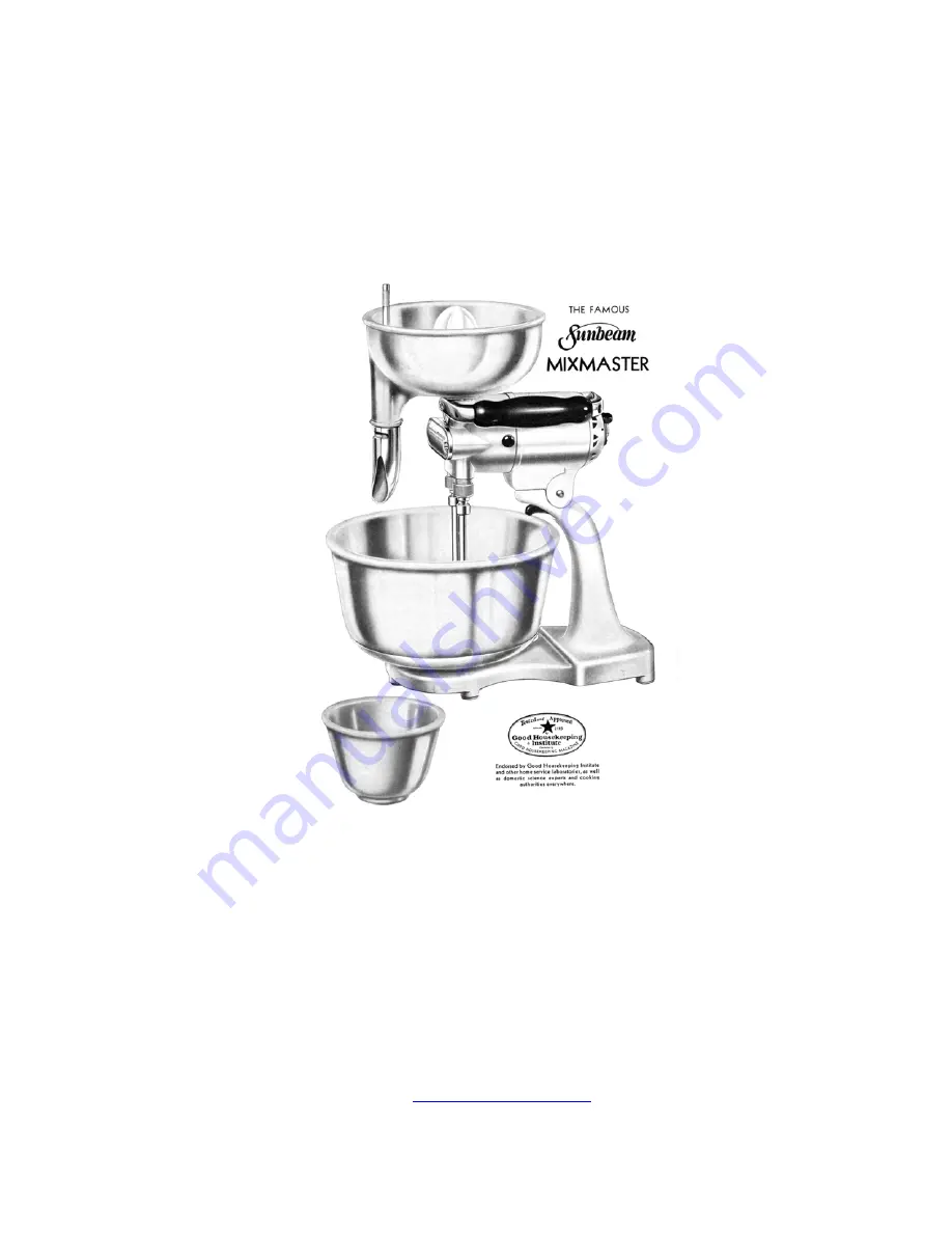
Instructions for Servicing Vintage
Sunbeam Mixmasters
Original Sunbeam Factory Service Information for Models:
1, 3A, 3B, 3 ‘Automatic’
Compiled by
Dave’s Repair Service
New Albany, PA
2004 All Rights Reserved
www.DavesRepair.com
Страница 1: ...s for Servicing Vintage Sunbeam Mixmasters Original Sunbeam Factory Service Information for Models 1 3A 3B 3 Automatic Compiled by Dave s Repair Service New Albany PA 2004 All Rights Reserved www Dave...
Страница 2: ...r Thus a constant speed is maintained even with variations in the load or line voltage and full power is available at all speeds The breaker points are mounted on a lever arm and so arranged on a disc...
Страница 3: ...a rotating disc to enable centrifugal force to act upon them the current is fed to the rotating governor through a pair of stationary brushes hence there are two governor brushes The wiring diagram b...
Страница 4: ...f the lamp does not light the circuit is open and a complete test should be made of the electric cord as in section 2 If light is illuminated to approximately half normal brightness that indicates tha...
Страница 5: ...ing part of the gear case then remove switch cover assembly 71 as in section 5 Grasp the governor disc 100 in one hand and insert a whipper in the frozen spindle sleeve and try to turn both in the sam...
Страница 6: ...ouch the other on any commutator bar or bars If test lamp lights a ground or conducting path is present between live parts and laminations a condition that should not exist and the armature should be...
Страница 7: ...rush springs and tighten brush screw 16 securely so screw will not loosen while motor is running 11 Fitting the Switch Mounting Bracket Assembly 105 in the Motor Put the Switch Mounting Bracket and re...
Страница 8: ...disc but as explained in the introduction to this bulletin close observation will show that only one arm is fitted with tungsten points The other points are larger and are made of cold rolled steel Th...
Страница 9: ...curely with the socket wrench supplied for adjusting thrust screw lock nut Thrust screw nut washer 88 and switch knob 70 are also held in p1ace by thrust screw lock nut 25 The motor bearings 45 may be...
Страница 10: ...and the motor To properly adjust screw 32 put the motor on the standard take the Special Gear box gauge or a Power Unit Attachment and slip it into the whipper spindle sleeve 20 Lower the motor head...
Страница 11: ...om the filter condenser the lead with the lug under screw 66 Next replace the terminal insulation box 96 and bring the field leads and condenser leads up thru the holes provided The leads may now be c...
Страница 12: ...ns Normally Except 1st Speed is Too Low Less than 275 R P M at whipper spindle sleeve 20 24 A Governor 100 needs replacement as in sections 5 5 A 13 13 B 14 14 A 25 Motor Does Not Run At All 25 A Swit...
Страница 13: ...urn motor to factory for service 29 Motor Runs but Whippers Do Not 29 A Worm gear 9 stripped or loose from metal hub Repair as in sections 4 16 and 17 THE TOOLS REQUIRED FOR USE WITH BULLETIN ARE One...
Страница 14: ...arm this breaker point will be celled the Fixed Contact throughout the remainder of this bulletin because the position of that contact point remains fixed for any particular speed its position being d...
Страница 15: ...ot to break or lose the thin rubber gasket 116 fitted around the circumference of the Bakelite disc A 4 To remove the fan housing and rear bearing bushing assembly key number 135 unscrew the three hex...
Страница 16: ...e that the broached flats on the inside lie parallel with armature shaft Tighten brush holders in place with set screws 22 using thin screwdriver as described in Section A 9 B 2 If front of motor is n...
Страница 17: ...ure with the other worm gear on left aide and assemble it to whipper spindle sleeve 13 again being sure that the gear is fitted to sleeve with set screw hole held exactly in front in order to get prop...
Страница 18: ...sh it back against motor housing Remove switch knob 70 from rear cover 120 if not already taken off then put rear cover on the end of the motor and fasten in place with the two round head rear cover s...
Страница 19: ...84 where cord enters motor Remove soft rubber insulating cover 95 and examine wire connections for grounds or shorts If connections appear to be in good order detach cord from motor by applying hot so...
Страница 20: ...of switch lever 105 If test lamp fails to light to full brilliance an open circuit must exist between governor contact points Clean the governor contacts and burnish them as instructed in J 2a D Motor...
Страница 21: ...n B 11 J 2 When speed has been adjusted according to Section B 11 and motor still jerks when running J 2a Governor tungsten contact points may be dirty or pitted A film of oil on surface of governor c...
Страница 22: ...l and if the condenser is shorted the lamp will light to full brilliance When either resistor or condenser need to be replaced change only those parts it will not be necessary to replace the complete...
Страница 23: ......
Страница 24: ......
Страница 25: ......
Страница 26: ......
Страница 27: ......
Страница 28: ......
Страница 29: ......
Страница 30: ......