


48
MAINTENANCE
6.5
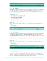
COMPRESSOR LUbRICANT
6.5.1
FACTORY FILL
The compressor is filled with the correct amount of lubricant at the factory before shipment. Palasyn 45
is the standard lubricant used to fill the compressors at the factory. Other lubricants are available as an
optional fill upon request. The type of lubricant used is indicated by a decal, which is typically located on the
sump tank.
CAUTION!
Never mix synthetic lubricants with hydrocarbon lubricants. Never mix synthetic lubricants
manufactured from different base products. Severe damage to the compressor system may result.
Lubricant manufacturers include a variety of additives in the blending process to enhance lubrication,
product life and performance. Mixing different types or brands of lubricants is not recommended due to the
possibility of a dilution of the additives or a reaction between additives of different types.
Environmental conditions in the area of compressor operation such as the presence of reactive gases or
vapors in the air may lead to chemical changes and premature degradation of the lubricant. The useful life of
synthetic lubricants may extend the normally recommended drain and replace period; however, the user is
encouraged to closely monitor the lubricant condition and to participate in an oil analysis program with the
fluid supplier. See
8.4 Compressor Lubricants on page 62
or more information.
6.5.2
CHECK
The oil level should be checked daily.
1.
Shut down the compressor (or check before the compressor is turned on).
2.
Wait two minutes after the compressor stops to allow the pressure to be relieved and the oil to settle.
3.
Observe the oil level in the fluid sight glass. The fluid sight glass should show ½ to ⅔ full.
4.
While the compressor is running, the oil should be visible in the sight glass.
6.5.3
FILL
Oil must be added to the compressor if the oil level is below the sight glass when the compressor is running.
1.
2.
Verify that compressor has no air pressure prior to removal of component parts.
3.
Clean any dirt from around the oil fill cap.
4.
Loosen the cap to make sure any remaining pressure is relieved through the vent hole, then remove.
5.
Add oil until ½ to ⅔ full.
6.
Replace cap and tighten securely.
6.5.4
CHANGE
Change the compressor oil as indicated by
or if fault A:4805 is shown on the
microprocessor
.
REMOVE OLD LUbRICANT
1.
2.
Remove the drain plug from the end of the drain line at the bottom of the sump tank.
3.
Open the drain valve and allow all oil to drain. Discard in an approved manner.
4.
Remove any remaining oil by splitting the discharge pipe at the compressor unit.
ADD NEW LUbRICANT
1.
Clean any dirt from around the oil fill cap.
2.
Loosen the cap to make sure any remaining pressure is relieved through the vent hole, then remove.
3.
Add oil until ½ to ⅔ full.
4.
Replace cap and tighten securely.
6.5.5
CONVERT
When converting to a different type of oil in the compressor, use the following procedures to ensure the
different oil types do not mix:
Содержание UD Series
Страница 6: ...vi About This Manual ...
Страница 12: ...4 Introduction ...
Страница 24: ...16 Specifications 2 2 DIMENSIONS OPEN AIR COOLED 230V Figure 2 1 GA 30 40 50UD AC VFD 230V R00 ...
Страница 25: ...17 Specifications 2 3 DIMENSIONS OPEN AIR COOLED 460V Figure 2 2 GA 30 40 50UD AC MPC VFD OPEN 460V R00 ...
Страница 26: ...18 Specifications 2 4 DIMENSIONS ENCLOSED AIR COOLED 460V Figure 2 3 GA 40 50 60UDAC ENC S1 R00 ...
Страница 27: ...19 Specifications 2 5 DIMENSIONS ENCLOSED HEAVY DUTY INLET OPTION 460V Figure 2 4 GA 40 50 60UDAC VFD ENC R00 ...
Страница 28: ...20 Specifications 2 6 DIMENSIONS ENCLOSED AIR COOLED HD INLET NO BUSSEL Figure 2 5 GA 60UDAC ENC VFD NB R00 ...
Страница 29: ...21 Specifications 2 7 PIPING AND INSTRUMENTATION AIR COOLED Figure 2 6 P I 15 40D AC MPC VFD R02 ...
Страница 42: ...34 Component Description ...
Страница 52: ...44 Operation ...
Страница 66: ...58 Troubleshooting ...
Страница 74: ...66 Parts Catalog 8 5 COMPRESSOR FRAME AND DRIVE ASSEMBLY Figure 8 1 AS801 25UD 50UD VFD R00 ...
Страница 76: ...68 Parts Catalog 8 6 CONTROL ASSEMBLY OPEN Figure 8 2 1072190415 609 R00 ...
Страница 78: ...70 Parts Catalog 8 7 STARTER ASSEMBLY ENCLOSED Figure 8 3 AS802 405060 PANEL R03 ...
Страница 80: ...72 Parts Catalog 8 8 AIR INLET ASSEMBLY 15 30HP 13 12 11 13 12 4 5 2 3 14 1 Figure 8 4 AS805 030D7H TE R00 ...
Страница 94: ...86 Parts Catalog 8 15 COOLING ASSEMBLY AIR COOLED Figure 8 11 AS804 50UDAC INLINE R00 ...
Страница 100: ...NOTES ...
Страница 101: ...NOTES ...


