16
CoMPoNENT DESCRIPTIoN
3.1
PORTABLE COMPRESSOR PACKAGE
The compressor is a single stage, oil-flooded lubricated rotary screw air compressor. The compressor
package is available as a portable wheel-mounted unit, utility mounted unit, or galvanized skid-mounted
unit for offshore applications. All models are enclosed in a weather-resistant acoustical enclosure.
The complete operating unit consists of a diesel engine for power, compressor assembly, air/oil separator
system, cooling system for the engine and compressor oil, instrumentation, pneumatic control system, and
acoustical enclosure.
3.2
ENGINE
The compressor is powered by a diesel engine. For detailed information on the engine refer to the Engine
operators Manual provided with each compressor.
3.2.1
ENGINE COOLING SYSTEM
The engine cooling system utilizes a conventional engine radiator, thermostat, water pump, and fan to
maintain the engine coolant at a desired operating temperature.
3.2.2
ENGINE TO COMPRESSOR DRIVE
The compressor and engine are connected through a non-lubricated spline coupling. It consists of a drive
ring registered and bolted directly to the engine flywheel and either a splined hub or a disc attached to the
compressor drive shaft. because of low starting torque, no clutch is required.
3.3
AIR END ASSEMBLY
The compressor assembly is an oil flooded, positive displacement, single stage rotary screw unit.
Components include a stator housing, male and female rotors, bearings, and bearing supports. Engine power
is transferred to the male rotor through a coupling and, if a gear-driven unit, through gears in the gear
housing. The male rotor drives the female rotor.
3.3.1
COMPRESSION CYCLE
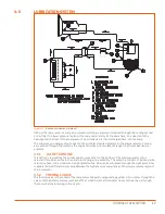
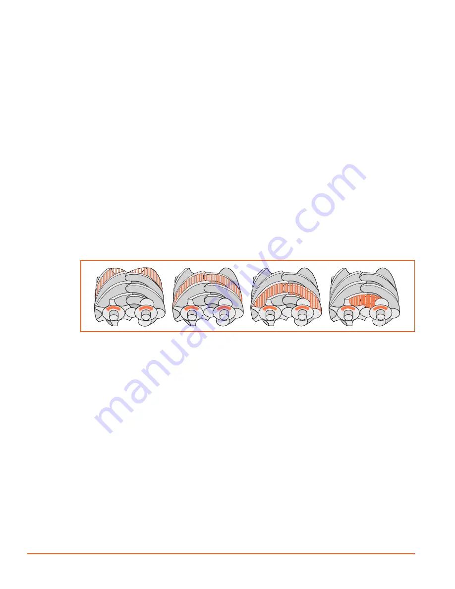
Figure 3-1.
COMPRESSION CyCLE
Air at atmospheric pressure is drawn in through the inlet and compressed by the rotation of the rotors.
During the compression cycle, oil is injected into the compressor performing three important functions:
1.
lubricate the rotating parts and bearings.
2.
Provide cooling for the compressed air.
3.
Seal the running clearances between the rotors.
3.4
DISCHARGE SYSTEM
3.4.1
reCeiVer/SuMP
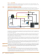
From the compressor discharge, oil-laden air enters the receiver/sump tank above the oil level and most
of the oil is separated from the air by gravity. The oil runs downward and accumulates for recirculation,
while the remaining oil mist passes through the separator element. The oil separator is located in the upper
portion of the receiver/sump. When air is demanded at the service line, it passes through the separator
element, which provides the final stages of air/oil separation.
3.4.2
MINIMUM PRESSURE VALVE
A minimum pressure valve is provided at the service air outlet (at the top of the separator). This valve
serves to maintain a minimum discharge pressure of 65 to 80 psig in operation, which is required to assure
proper air/oil separation. At normal operating pressure of 90 to 150 psig, this valve is wide open, effectively
removing any restriction to airflow.
Содержание D260UJD4PTOW
Страница 4: ......
Страница 6: ...vi About This Manual ...
Страница 14: ...6 Safety ...
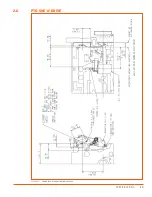
Страница 21: ...13 Specifications 2 6 PTO SAE A DRIVE Figure 2 5 Power Take Off Auxiliary Drive Specs ...
Страница 22: ...14 Specifications ...
Страница 32: ...24 Component Description ...
Страница 44: ...36 Installation and Operation ...
Страница 58: ...50 Troubleshooting ...
Страница 125: ...117 Parts Catalog ...
Страница 134: ...NOTES ...
Страница 135: ...NOTES ...

