


SECTION 5
ES-8 MOBILE APPLICATION MANUAL R00
21
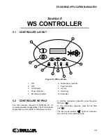
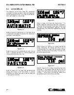
Figure 5-8:
Refer to
. If there is no keypad activity, the
display will return to normal view in about one
minute. If the Start or Stop buttons are pressed, the
display also returns to normal view. If either of these
occur, the setting will not be altered.
If there are any warnings or recommended service
instructions, these will be periodically displayed on
the normal view.
The list of displays may be navigated from either
direction by using the Up "
" or Down "
"
arrow keys. For example, to change language from
normal view, press the Up arrow pad once, press the
Enter key "
", select your language, and press
Enter again. The number of displays varies with
compressor model, but will follow this pattern.
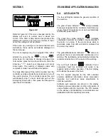
The large Emergency Stop button located near the
controller overrides all electronic functions to turn off
the control devices. The controller senses this, and
will display E-stop. To reset, twist and pull out the
Emergency Stop button, then press the Stop pad to
reset the WS Controller.
5.4
LED LIGHTS
The four LED lights indicate the general condition of
the machine.
The green Power indicator "
" simply indicates
that power is applied to the controller. It will blink very
slowly if the WS Controller is set up to automatically
restart after power failure.
The green Run mode indicator "
" indicates
compressor operation is enabled. It lights steadily if
the motor is running. If the motor stops while in
Automatic mode, this LED will blink to indicate that
the motor may restart.
The yellow Maintenance indicator "
" comes on
whenever there is recommended maintenance or a
warning. The text display will periodically indicate the
recommended actions or the cause of the warning.
The red Fault indicator "
" indicates that a
compressor fault has occurred and needs to be
repaired before further operation. The text display
will indicate the cause of the fault.
The PC support program for the WS controller
provides additional information about compressor
operation and advanced setup adjustments to
optimize operation.
Software part numbers are shown in the display
following a power interruption or other interruption of
communication with the controller. The P/N remains
on the display until satisfactory communications are
established with the Input/Output module.
Содержание 30XH
Страница 10: ...NOTES 10 ...
Страница 22: ...NOTES 22 ...
Страница 33: ...NOTES 33 ...
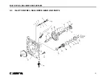
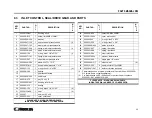
Страница 34: ...INLET CONTROL SEAL DRIVE GEAR AND PARTS 34 8 3 INLET CONTROL SEAL DRIVE GEAR AND PARTS ...
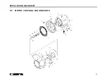
Страница 36: ...MOTOR COUPLING FAN AND PARTS 36 8 4 MOTOR COUPLING FAN AND PARTS ...
Страница 40: ...COMPRESSOR COOLER SYSTEM AND PARTS 40 8 6 COMPRESSOR COOLER SYSTEM AND PARTS ...
Страница 42: ...PNEUMATIC CONTROL SYSTEM AND PARTS 42 8 7 PNEUMATIC CONTROL SYSTEM AND PARTS ...
Страница 44: ...CONTROL STARTER MFV 44 8 8 CONTROL STARTER MFV ...
Страница 46: ...DECAL GROUP 46 8 9 DECAL GROUP ...
Страница 48: ...DECAL GROUP 48 8 9 DECAL GROUP CONTINUED ...
Страница 50: ...WIRING DIAGRAM FULL VOLTAGE STANDARD 50 8 10 WIRING DIAGRAM FULL VOLTAGE STANDARD ...
Страница 51: ...NOTES 51 ...


