background image

PRODUCT USER MANUAL

SECTION 3

110

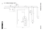
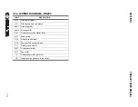
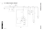
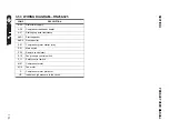
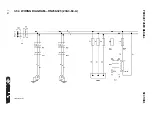
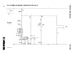
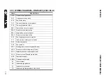
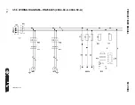
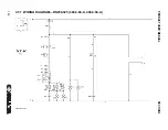
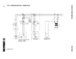
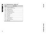
3.52 WIRING DIAGRAM—RN200

02250195-310

Содержание RD Series

Страница 1: ...CE MANUAL REFRIGERATED DRYERS RH HIGH TEMPERATURE RN NON CYCLING RD DIGITAL CYCLING PART NUMBER KEEP FOR FUTURE REFERENCE SULLAIR CORPORATION 02250195 401 R00 The information in this manual is current as of its publication date and applies to compressor serial number RH 0611SA0198 RN 4810SA0001 RD 0711SA0263 and all subsequent serial numbers ...

Страница 2: ...ed at Michigan City Indiana Instruction includes training on the function and installation of Sullair service parts troubleshooting common faults and malfunctions and actual equipment operation These seminars are recommended for maintenance contractor maintenance and service personnel For detailed course outlines schedule and cost information contact SULLAIR TRAINING DEPARTMENT 1 888 SULLAIR or 21...

Страница 3: ...ED RH15 50 20 2 8 ED RH75 100 22 2 9 ID RH15 50 24 2 10 ID RH75 100 26 2 11 P I RH15 75 28 2 12 P I RH100 30 2 13 WIRING DIAGRAM 32 2 14 TROUBLESHOOTING 37 2 15 SETTINGS 38 2 16 SPARE PARTS SECTION 3 RN RD SERIES REFRIGERATED NON CYCLING COMPRESSED AIR DRYER 41 3 1 INTRODUCTION 41 3 2 SPECIFICATIONS 42 3 3 SAFETY INSTRUCTIONS 42 3 4 ISSUES TO AVOID 42 3 5 RECEIVING AND INSPECTION 42 3 6 TRANSPORTA...

Страница 4: ...50 64 3 27 ED RN 175 66 3 28 ED RN 200 68 3 29 ED RN 250 70 3 30 ED RN 325 230 72 3 31 ED RN 325 460 74 3 32 ID RN5 15 76 3 33 ID RN25 78 3 34 ID RN35 50 80 3 35 ID RN75 100 82 3 36 ID RN125 84 3 37 ID RN150 86 3 38 ID RN175 200 88 3 39 ID RN250 400 90 3 40 P I RN5 10 15 25 92 3 41 P I RN35 75 94 3 42 P I RN100 200 96 3 43 P I RN250 325 97 3 44 P I RD400 500 700 850 98 3 45 P I RD700 850 99 3 46 P...

Страница 5: ... RD400 168 4 4 ED RD500 170 4 5 ED RD700 172 4 6 ED RD700 AIR COOLED 174 4 7 ED RD850 176 4 8 ED RD850 AIR COOLED 178 4 9 ED RD1000 180 4 10 ED RD1000 AIR COOLED 182 4 11 ED RD1200 AIR COOLED 184 4 12 ED RD1600 AIR COOLED 186 4 13 ED RD2000 AIR COOLED 188 4 14 ED RD2400 AIR COOLED 190 4 15 ED RD3000 AIR COOLED 192 4 16 ED RD3800 AIR COOLED 194 4 17 ED RD5000 AIR COOLED 196 4 18 ED RD6000 AIR COOLE...

Страница 6: ...2000 2400 3000 3800 5000 6000 460 3 60 A 400 3 50 A 242 4 41 WIRING DIAGRAM RD 500 700 850 1000 1200 1600 2000 2400 3000 3800 5000 6000 460 3 60 A 400 3 50 A 244 4 42 WIRING DIAGRAM RD700 850 230 3 60 W 246 4 43 WIRING DIAGRAM RD700 850 230 3 60 W 248 4 44 WIRING DIAGRAM RD 700 850 1000 1200 1600 2000 2400 3000 3800 5000 6000 460 3 60 W 400 3 50 W 250 4 45 WIRING DIAGRAM RD 700 850 1000 1200 1600 ...

Страница 7: ...peration Manual The dryer is only to be operated serviced and repaired by trained personnel who are familiar with this type of equipment and understand fully its operation and any potential dangers 1 1 SAFETY INFORMATION The end user and operator must observe all National State and Local industrial and safety regulations dealing with the operation of pressure vessels under compressed air service A...

Страница 8: ...8 NOTES ...

Страница 9: ...Section 2 9 RH SERIES HIGH TEMPERATURE RH SERIES REFRIGERATED HIGH TEMPERATURE COMPRESSED AIR DRYER RH 0015 115 60 A RH 0025 115 60 A RH 0035 115 60 A RH 0075 115 60 A RH 0100 115 60 A ...

Страница 10: ...ture is removed with an automatic drain The hot saturated air is then passed directly into the RH series of dryers RH series of non cycling refrigerant compressed air dryers have been designed to remove water vapor from industrial compressed air that is free of reactive contaminants like ammonia gaseous acid dust rust or any other chemical or mineral products capable of reacting or clogging the he...

Страница 11: ...SECTION 2 RH SERIES HIGH TEMPERATURE 11 2 3 TYPICAL INSTALLATION The RH series of Dryers operate without the need for any after coolers ...

Страница 12: ... is necessary to allow free air circulation and easy access for servicing 2 The ambient temperature in the room should not exceed 120 F and should not be below 40 F taking into account the heat radiated by the dryer About 18 watts for each SCFM under ISO 7183 5 condition or 40 watt for each liter sec under ISO 7183 A condition 2 4 4 INSTALLATION In addition to the general mechanical construction p...

Страница 13: ...alified refrigerant engineer Refer to section Environmental protection of this manual 3 Every six months check the correct operation of the condenser drain trap Replace timer or solenoid valve in case of clogging or malfunctioning 4 Every six months check and clean the drain strainer or the electronic sensor by undoing the access screw and rinsing the filter with tap water to remove the trapped di...

Страница 14: ... pres sure expansion valve regulates this process 2 4 11 COMPRESSED AIR CIRCUIT 1 The hot saturated compressed air from the compressor is forced into the air cooled after cooler where it is pre cooled to approxi mately ambient temperature 2 This pre cooled compressed air enters the high efficiency moisture separator where condensed moisture is stripped from the air stream and purged out via the el...

Страница 15: ...t excessive pressure by a security switch that stops the compressor in case of too high a pressure In case this safety switch has tripped it has to be manually reset before switching on the dryer 2 5 4 FILTER DRYER In order to keep the refrigerant circuit void of all moisture a filter drier is used in line This filter also traps any solid particles that may have migrated in the circuit during oper...

Страница 16: ...n air to air heat exchanger which pre cools the incoming hot air with the outgoing cold air thereby saving a significant load on the compressor 2 An Evaporator which is an air to refrigerant heat exchanger that cools the pre cooled compressed air 3 An integrated separator that removes all condensates and requires no additional maintenance AIR REF AIR INLET DRAIN PORT AIR OUTLET REFRIGERANT GAS OUT...

Страница 17: ...n the green button to start the dryer b The start light will indicate that the dryer is running 3 To stop the dryer first stop the airflow either shut down the air compressor or close the inlet outlet or by pass valve When the air flow is stopped push the green button to the stop position NOTE 1 Avoid turning OFF the dryer when com pressed air is still flowing through it 2 To switch the already pr...

Страница 18: ...RH SERIES HIGH TEMPERATURE SECTION 2 18 2 7 ED RH15 50 02250195 252 R00 ...

Страница 19: ...TIC GUAGE 1 16 M ONB 0200 ON OFF BUTTON 1 17 M CFR 0050H CABINET FRONT 1 18 M CLE 0050H CABINET SIDE LEFT 1 19 M CRI 0050H CABINET SIDE RIGHT 1 20 M CRE 0050H CABINET REAR 1 21 M CTO 0050H CABINET TOP 1 22 M CBA 0050H CABINET BASE 1 23 M CBL 0050H CABINET LEG 4 24 M HP1 0050H CABINETHORIZONTAL PROFILE 1 2 25 M HP2 0050H CABINET HORIZONTAL PROFILE 2 2 26 M CTC 3000 CABINET TOP CORNER 4 27 M CPS 300...

Страница 20: ...RH SERIES HIGH TEMPERATURE SECTION 2 20 2 8 ED RH75 100 02250195 253 R00 ...

Страница 21: ...WITCH 1 16 M THG 0325 THERMOSTATIC GUAGE 1 17 M ONB 0200 ON OFF BUTTON 1 18 M CFR 0100H CABINET FRONT 1 19 M CLE 0100H CABINET SIDE LEFT 1 20 M CRI 0100H CABINET SIDE RIGHT 1 21 M CRE 0100H CABINET REAR 1 22 M CTO 0100H CABINET TOP 1 23 M CBA 0100H CABINET BASE 1 24 M CBL 0100H CABINET LEG 4 25 M HP1 0100H CABINETHORIZONTAL PROFILE 1 2 26 M HP2 0100H CABINET HORIZONTAL PROFILE 2 2 27 M CTC 3000 CA...

Страница 22: ...RH SERIES HIGH TEMPERATURE SECTION 2 22 2 9 ID RH15 50 02250195 252 R00 ...

Страница 23: ...D RH50 02250193 796 115V 1Ph 60Hz AIR COOLED RH35 02250193 797 115V 1Ph 60Hz AIR COOLED RH25 02250193 798 115V 1Ph 60Hz AIR COOLED RH15 WITHOUT PALLET SIZE WITH PALLETT SIZE GROSS WEIGHT NET WEIGHT DRYER 17 52 17 52 37 6 445 445 955 20 08 20 08 44 68 510 510 1135 163 LB 141 LB RH50 161 LB 139 LB RH35 159 LB 137 LB RH25 159 LB 137 LB RH15 ...

Страница 24: ...RH SERIES HIGH TEMPERATURE SECTION 2 24 2 10 ID RH75 100 02250195 253 ...

Страница 25: ...ER RATINGS COOLING DECAL 02250193 799 115V 1Ph 60Hz AIR COOLED RH75 02250193 800 115V 1Ph 60Hz AIR COOLED RH100 WITHOUT PALLET SIZE WITH PALLETT SIZE GROSS WEIGHT NET WEIGHT DRYER 20 08 22 05 35 83 510 625 755 24 21 27 76 42 32 615 705 1075 238 LB 213 LB RH100 217 LB 193 LB RH75 ...

Страница 26: ...RH SERIES HIGH TEMPERATURE SECTION 2 26 2 11 P I RH15 75 02250195 284 ...

Страница 27: ...3 AFTERCOOLER 4 FAN MOTOR 5 FAN MOTOR SWITCH 6 DEHYDRATOR 7 THERMOSTATIC EXPANSION VALVE 8 EVAPORATOR 9 AIR AIR EXCHANGER 10 DEW POINT INDICATOR NOTE MARK TAG COMPONENT CONTAINER WITH SULLAIR P N AND REVISION MODEL REFRIGERANT TYPE LB RH15 R134A 1 102 RH25 1 102 RH35 1 102 RH50 0 992 RH75 1 543 ...

Страница 28: ...RH SERIES HIGH TEMPERATURE SECTION 2 28 2 12 P I RH100 02250195 285 ...

Страница 29: ...CONDENSER 3 AFTERCOOLER 4 FAN MOTOR 5 FAN MOTOR SWITCH 6 DEHYDRATOR 7 THERMOSTATIC EXPANSION VALVE 8 EVAPORATOR 9 AIR AIR EXCHANGER 10 DEW POINT INDICATOR 11 LIQUID RECEIVER 12 BY PASS VALVE NOTE MARK TAG COMPONENT CONTAINER WITH SULLAIR P N AND REVISION REFRIGERANT TYPE R134A 2 435 lb ...

Страница 30: ...RH SERIES HIGH TEMPERATURE SECTION 2 30 2 13 WIRING DIAGRAM 02250195 303 R00 ...

Страница 31: ...elay A20 1 Electronic drain power supply 1 A20 2 Electronic drain power supply 2 M01 Compressor motor M10 1 Fan motor 1 M10 2 Fan motor 2 S01 Main switch S10 Fan pressure switch S11 High pressure safety switch S21 High air temperature thermostat P Compressor protection HP Indicates high pressure TH Indicates high temperature in the circuit ...

Страница 32: ... dryer inlet conditions are within the recommended range Designed conditions and correction factors are described in product liter ature A high ambient temperature may cause the refrigerant system to oper ate at higher than normal pressures Results will be a higher than normal evaporator temperature Important there should be adequate air circulation around the dryer and proper ventilation in the e...

Страница 33: ...ve a qualified refrigerant technician check the complete dryer thoroughly Dryer on light is lit but fan does not come ON Fan has to run if refriger ant high pressure has reached upper set point Check the compressed air flows through the dryer Check to make sure that the fan blades are free to rotate Fan is automatically turned ON OFF in order to keep the refrigerant pres sure to a minimum value Th...

Страница 34: ...round the dryer so the dryer can be isolated for service without shutting down the air supply During dryer operation valves must be set so all air goes into the system Check tightness of the bypass system Free moisture remains in pipe lines Blow out the system Before the dryer is placed inline blow out all the moisture from the system and from the compressed air piping Excessive free moisture Chec...

Страница 35: ...ssure and lower the dew point Adjust valves in turn increments to allow 15 minutes for pressure stabili zation with full air flowing Be sure that gauge indicates that pressure stays in green zone High pressure drop Excessive compressed air flow or too low air inlet pressure Check actual pressure and flow through the dryer This dryer is designed for a maximum air flow If too much air is pumped into...

Страница 36: ...ecting devices can get switched off Excessive ambient tem perature Designed conditions and correction factors as described in the product literature must be strictly followed Ensure that the dryer is working well within the maximum con ditions A high ambient temperature may cause the refrigerant system to oper ate at higher than normal pressures Result will be a higher than normal evaporator tempe...

Страница 37: ...23 2 psi N A N A 4 sec 5 min N A N A RH 0075 5 10 C 41 50 F 2 05 bar 29 7 psi 9 12 bar 130 5 174 psi 25 bar 363 psi 1 6 bar 23 2 psi N A N A 4 sec 5 min N A N A RH 0100 5 10 C 41 50 F 2 05 bar 29 7 psi 9 12 bar 130 5 174 psi 25 bar 363 psi 1 6 bar 23 2 psi N A N A 4 sec 5 min N A N A Table 2 1 DP Power 60H GROUP STANDARD VOLTAGE Capacity SCFM Rated Conditions AIR COOLED MODEL REF SULLAIR PART WATE...

Страница 38: ...Exchanger N A N A N A N A N A N A Flexible steel tube inlet N A N A N A N A N A N A Flexible steel tube outlet N A N A N A N A N A N A Expansion valve M EXV 0075 M EXV 0075 M EXV 0075 M EXV 0075 M EXV 0075 M EXV 0075 By pass valve N A N A N A N A N A N A separator N A N A N A N A N A N A Liquid Receiver N A N A N A N A N A N A High Pressure Security switch M HPS 0200 M HPS 0200 M HPS 0200 M HPS 02...

Страница 39: ... 0050H M CRE 0050H M CRE 0050H M CRE 0050H M CRE 0100H M CRE 0100H Cabinet Top M CTO 0050H M CTO 0050H M CTO 0050H M CTO 0050H M CTO 0100H M CTO 0100H Cabinet Base M CBA 0050H M CBA 0050H M CBA 0050H M CBA 0050H M CBA 0100H M CBA 0100H Cabinette fastener M FAS 1000 M FAS 1000 M FAS 1000 M FAS 1000 M FAS 1000 M FAS 1000 Cabinette Stud and Nut M STU 1000 M STU 1000 M STU 1000 M STU 1000 M STU 1000 M...

Страница 40: ...40 NOTES ...

Страница 41: ...assured of clean dry air with consistent dewpoint between 36 40 F The unique three in one heat exchanger combination Air to Air pre cooler re heater Heat Exchanger Air to Refrigerant high efficiency Heat Exchanger Integrated Separator located at the coldest point to maximize moisture extraction heats up the exiting air thereby eliminating the chances of freezing even in relatively cooler ambient c...

Страница 42: ...e of the protective alarms equipment or devices should be tampered with These pro tective items have been designed and installed on this dryer for your safety 3 Do not operate the dryer at pressures tem peratures of flow other than the ones men tioned on the data label 3 5 RECEIVING AND INSPECTION Sullair dryers are factory tested prior to shipment However during shipment there are chances that th...

Страница 43: ...n only The minimum and maximum values stated must be observed as well as the safety precautions described in this manual 3 10 PRODUCT FEATURES 3 10 1 REFRIGERANT COMPRESSOR The refrigerant compressor is fully hermetically sealed and requires no maintenance 3 10 2 CONDENSER 1 Air cooled models The refrigerant con denser is equipped with fans that are cycled on and off to maintain a minimum high sid...

Страница 44: ...ve For dryers with capacities less than 35 CFM the unit must be completely depressurized before any attempt is made to clean the condensate separator and the drain trap 3 10 10 HEAT EXCHANGER MODULAR DESIGN The dryers are equipped with compact modular design heat exchangers This assembly has been specially designed to dry compressed air and consists of 1 An air air heat exchanger which pre cools t...

Страница 45: ...rates changes states from liquid to gas by absorbing heat from the compressed air The gaseous refrigerant is sucked into the compressor and the cycle carries on 9 In order to keep the evaporation pressure steady and maintain the refrigerant tempera ture in the heat exchanger a hot gas by pass valve injects hot gaseous refrigerant into the low pressure refrigerant circuit 3 12 COMPRESSED AIR HEAT E...

Страница 46: ...wner and the Standard Building Code The installer shall obtain all permits and inspections required for the work and shall pay all costs and fees thereof 3 15 OPERATING PRECAUTIONS This dryer has been thoroughly tested packaged and inspected prior to shipment Nevertheless the unit could be damaged during transportation check the integrity of the dryer during first start up and monitor operation du...

Страница 47: ...low easy maintenance and for possible isolation of the dryer without interrupting the compressed air flow 5 In Line Filters install one compressed air fil ter in line particulate filter before the dryer to protect it against dirt and possible clog ging of heat exchanger Install an After filter coalescing filter that can act as a backup during short periods when the by pass valve is open to perform...

Страница 48: ... the dryer is isolated 5 Ensure that the manual valve of the conden sate drain circuit is open 6 Remove any packaging and other material which could obstruct the area around the dryer 7 Activate the mains switch 8 Turn on the main switch pos 1 on the con trol panel 9 Check that the mains power light of the ON OFF button is ON 10 Wait at least two hours before starting the dryer compressor crankcas...

Страница 49: ...d cycle ON OFF on RD series The dryer must remain ON during the full usage period of the compressed air even if the air compressor works intermittently WARNING For short periods of inactivity max 2 3 days we recommend that power is main tained to the dryer and the control panel Otherwise before re starting the dryer it is necessary to wait at least 2 3 hours for the compressor crankcase heater to ...

Страница 50: ...PRODUCT USER MANUAL SECTION 3 50 3 20 ED RN 5 15 02250195 257 R00 ...

Страница 51: ...13 M ONB 0200 ON OFF BUTTON 1 14 M WSP 0050 WATER SEPARATOR 1 15 M CFR 0015 CABINET FRONT 1 16 M CLE 0015 CABINET SIDE LEFT 1 17 M CRI 0015 CABINET SIDE RIGHT 1 18 M CRE 0015 CABINET REAR 1 19 M CTO 0015 CABINET TOP 1 20 M CBA 0015 CABINET BASE 1 21 M CBL 0015 CABINET LEG 4 22 M HP1 0015 CABINET HORIZONTAL PROFILE 4 23 M CTC 3000 CABINET TOP CORNER 4 24 M CPS 3000 CABINET HANDLE 3 25 M PDC 0200 PL...

Страница 52: ...PRODUCT USER MANUAL SECTION 3 52 3 21 ED RN 25 02250195 258 R00 ...

Страница 53: ...EFT 1 17 M CRI 0025 CABINET SIDE RIGHT 1 18 M CRE 0025 CABINET REAR 1 19 M CTO 0025 CABINET TOP 1 20 M CBA 0025 CABINET BASE 1 21 M CBL 0025 CABINET LEG 4 22 M HP1 0025 CABINET HORIZONTAL PROFILE 1 2 23 M HP2 0025 CABINET HORIZONTAL PROFILE 2 2 24 M CTC 3000 CABINET TOP CORNER 4 25 M CPS 3000 CABINET HANDLE 3 26 M PDC 0200 PLASTIC DISPLAY COVER 1 27 M SCR 0200 SCREW TYPE 1 24 28 M STU 3000 CABINET...

Страница 54: ...PRODUCT USER MANUAL SECTION 3 54 3 22 ED RN 35 50 02250195 259 R00 ...

Страница 55: ...AR 1 19 M CTO 0025 CABINET TOP 1 20 M CBA 0025 CABINET BASE 1 21 M CBL 0025 CABINET LEG 4 22 M HP1 0025 CABINET HORIZONTAL PROFILE 1 2 23 M HP2 0025 CABINET HORIZONTAL PROFILE 2 2 24 M CTC 3000 CABINET TOP CORNER 4 25 M CPS 3000 CABINET HANDLE 3 26 M PDC 0200 PLASTIC DISPLAY COVER 1 27 M SCR 0200 SCREW TYPE 1 24 28 M STU 3000 CABINET STUD AND NUT 12 29 M FAS 3000 CABINET FASTENER 12 30 M CSC 0035 ...

Страница 56: ...SECTION 3 PRODUCT USER MANUAL 56 3 23 ED RN 75 02250195 260 R00 ...

Страница 57: ...100 CABINET SIDE LEFT 1 19 M CRI 0100 CABINET SIDE RIGHT 1 20 M CRE 0100 CABINET REAR 1 21 M CTO 0100 CABINET TOP 1 22 M CBA 0100 CABINET BASE 1 23 M CBL 0100 CABINET LEG 4 24 M HP1 0100 CABINET HORIZONTAL PROFILE 1 2 25 M HP2 0100 CABINET HORIZONTAL PROFILE 2 2 26 M CTC 3000 CABINET TOP CORNER 4 27 M CPS 3000 CABINET HANDLE 3 28 M PDC 0200 PLASTIC DISPLAY COVER 1 29 M SCR 0200 SCREW TYPE 1 24 30 ...

Страница 58: ...SECTION 3 PRODUCT USER MANUAL 58 3 24 ED RN 100 02250195 260 R00 ...

Страница 59: ...9 M CFR 0100 CABINET FRONT 1 20 M CLE 0100 CABINET SIDE LEFT 1 21 M CRI 0100 CABINET SIDE RIGHT 1 22 M CRE 0100 CABINET REAR 1 23 M CTO 0100 CABINET TOP 1 24 M CBA 0100 CABINET BASE 1 25 M CBL 0100 CABINET LEG 4 26 M HP1 0100 CABINET HORIZONTAL PROFILE 1 2 27 M HP2 0100 CABINET HORIZONTAL PROFILE 2 2 28 M CTC 3000 CABINET TOP CORNER 4 29 M CPS 3000 CABINET HANDLE 3 30 M PDC 0200 PLASTIC DISPLAY CO...

Страница 60: ...SECTION 3 PRODUCT USER MANUAL 60 3 25 ED RN 125 02250195 261 R00 ...

Страница 61: ...M CFR 0150 CABINET FRONT 1 20 M CLE 0150 CABINET SIDE LEFT 1 21 M CRI 0150 CABINET SIDE RIGHT 1 22 M CRE 0150 CABINET REAR 1 23 M CTO 0150 CABINET TOP 1 24 M CBA 0150 CABINET BASE 1 25 M CBL 0150 CABINET LEG 4 26 M HP1 0150 CABINET HORIZONTAL PROFILE 1 2 27 M HP2 0150 CABINET HORIZONTAL PROFILE 2 2 28 M CTC 3000 CABINET TOP CORNER 4 29 M CPS 3000 CABINET HANDLE 5 30 M PDC 0200 PLASTIC DISPLAY COVE...

Страница 62: ...SECTION 3 PRODUCT USER MANUAL 62 3 26 ED RN 150 02250195 262 R00 ...

Страница 63: ... 0200 ON OFF BUTTON 1 19 M CFR 0150 CABINET FRONT 1 20 M CLE 0150 CABINET SIDE LEFT 1 21 M CRI 0150 CABINET SIDE RIGHT 1 22 M CRE 0150 CABINET REAR 1 23 M CTO 0150 CABINET TOP 1 24 M CBA 0150 CABINET BASE 1 25 M CBL 0150 CABINET LEG 4 26 M HP1 0150 CABINET HORIZONTAL PROFILE 1 2 27 M HP2 0150 CABINET HORIZONTAL PROFILE 2 2 28 M CTC 3000 CABINET TOP CORNER 4 29 M CPS 3000 CABINET HANDLE 5 30 M PDC ...

Страница 64: ...PRODUCT USER MANUAL SECTION 3 64 3 27 ED RN 175 02250195 263 R00 ...

Страница 65: ...TON 1 19 M CFR 0200 CABINET FRONT 1 20 M CLE 0200 CABINET SIDE LEFT 2 21 M CRI 0200 CABINET SIDE RIGHT 22 M CRE 0200 CABINET REAR 1 23 M CTO 0200 CABINET TOP 1 24 M CBA 0200 CABINET BASE 1 25 M CBL 0200 CABINET LEG 4 26 M HP1 0200 CABINET HORIZONTAL PROFILE 1 2 27 M HP2 0200 CABINET HORIZONTAL PROFILE 2 2 28 M CTC 3000 CABINET TOP CORNER 8 29 M CPS 3000 CABINET HANDLE 4 30 M PDC 0200 PLASTIC DISPL...

Страница 66: ...SECTION 3 PRODUCT USER MANUAL 66 3 28 ED RN 200 02250195 263 R00 ...

Страница 67: ...TON 1 19 M CFR 0200 CABINET FRONT 1 20 M CLE 0200 CABINET SIDE LEFT 2 21 M CRI 0200 CABINET SIDE RIGHT 22 M CRE 0200 CABINET REAR 1 23 M CTO 0200 CABINET TOP 1 24 M CBA 0200 CABINET BASE 1 25 M CBL 0200 CABINET LEG 4 26 M HP1 0200 CABINET HORIZONTAL PROFILE 1 2 27 M HP2 0200 CABINET HORIZONTAL PROFILE 2 2 28 M CTC 3000 CABINET TOP CORNER 8 29 M CPS 3000 CABINET HANDLE 4 30 M PDC 0200 PLASTIC DISPL...

Страница 68: ...PRODUCT USER MANUAL SECTION 3 68 3 29 ED RN 250 02250195 264 R00 ...

Страница 69: ...Y 1 SEE REF TABLE COMPRESSOR 1 2 M CON 0325 CONDENSOR 1 3 SEE REF TABLE FAN MOTOR ASSEMBLY 1 4 M DRI 1000 DRIER DEHYDRATOR 1 5 M EXC 0125 HEAT EXCHANGER 2 6 M EXV 0850 EXPANSION VALVE 1 7 M BYY 1000 BY PASS VALVE 1 8 M RCV 0850 LIQUID RECEIVER 1 9 M HPS 1000 HIGH PRESSURE SECURITY SWITCH 1 10 M FNS 0400 FAN ON OFF SWITCH 1 11 M LPS 1000 LOW PRESSURE SWITCH 1 12 M THS 0325 THERMOSTATIC SWITCH 1 13 ...

Страница 70: ...SECTION 3 PRODUCT USER MANUAL 70 3 30 ED RN 325 230 02250195 264 R00 ...

Страница 71: ...E 1 19 M CFR 0400 CABINET FRONT 1 20 M CLE 0400 CABINET SIDE 2 21 M CRE 0400 CABINET REAR 1 22 M CTO 0400 CABINET TOP 1 23 M CBA 0400 CABINET BASE 1 24 M CBL 0400 CABINET LEG 4 25 M HP1 0400 CABINET HORIZONTAL PROFILE 1 2 26 M HP2 0400 CABINET HORIZONTAL PROFILE 2 2 27 M CPS 3000 CABINET HANDLE 8 28 M CTC 3000 CABINET TOP CORNER 4 29 M STU 3000 CABINET STUD AND NUT 12 30 M FAS 3000 CABINET FASTENE...

Страница 72: ...PRODUCT USER MANUAL SECTION 3 72 3 31 ED RN 325 460 02250195 264 R00 ...

Страница 73: ...SIDE 1 21 M CRE 0400 CABINET REAR 1 22 M CTO 0400 CABINET TOP 1 23 M CBA 0400 CABINET BASE 1 24 M CBL 0400 CABINET LEG 4 25 M HP1 0400 CABINET HORIZONTAL PROFILE 1 2 26 M HP2 0400 CABINET HORIZONTAL PROFILE 2 2 27 M CPS 3000 CABINET HANDLE 8 28 M CTC 3000 CABINET TOP CORNER 4 29 M STU 3000 CABINET STUD AND NUT 12 30 M FAS 3000 CABINET FASTENER 12 31 M NUT 3000 CAGE NUT AND SCREW 16 32 M SCR 3000 S...

Страница 74: ...SECTION 3 PRODUCT USER MANUAL 74 3 32 ID RN5 15 02250195 257 R00 ...

Страница 75: ...V 1Ph 60Hz AIR COOLED RN5 02250193 809 115V 1Ph 60Hz AIR COOLED RN10 02250193 810 115V 1Ph 60Hz AIR COOLED RN15 02250193 869 220V 1Ph 50Hz AIR COOLED RN15 WITHOUT PALLET SIZE WITH PALLETT SIZE GROSS WEIGHT NET WEIGHT 13 8 x 13 8 x 24 350mm x 350mm x 610mm 17 52 x 17 52 x 31 5 445mm x 445mm x 800mm 85 LB 70 5 LB ...

Страница 76: ...PRODUCT USER MANUAL SECTION 3 76 3 33 ID RN25 02250195 258 R00 ...

Страница 77: ...AL 02250193 812 115V 1Ph 60Hz AIR COOLED RN25 02250193 870 220V 1Ph 50Hz AIR COOLED RN25 02250193 835 208 230V 1Ph 60Hz AIR COOLED RN25 WITHOUT PALLET SIZE WITH PALLETT SIZE GROSS WEIGHT NET WEIGHT 15 55 x 13 8 x 24 350mm x 395mm x 610mm 17 52 x 18 9 x 31 5 445mm x 480mm x 800mm 95 LB 74 LB ...

Страница 78: ...PRODUCT USER MANUAL SECTION 3 78 3 34 ID RN35 50 02250195 259 R00 ...

Страница 79: ...1Ph 60Hz AIR COOLED RN35 02250193 871 220V 1Ph 50Hz AIR COOLED RN35 02250193 814 115V 1Ph 60Hz AIR COOLED RN50 02250193 838 208 230V 1Ph 60Hz AIR COOLED RN50 02250193 872 220V 1Ph 50Hz AIR COOLED RN50 WITHOUT PALLET SIZE WITH PALLETT SIZE GROSS WEIGHT NET WEIGHT 15 35 x 17 71 x 23 23 390mm x 450mm x 590mm 19 23 x 21 26 x 30 7 490mm x 540mm x 780mm 109 LB 94 LB ...

Страница 80: ...PRODUCT USER MANUAL SECTION 3 80 3 35 ID RN75 100 02250195 260 ...

Страница 81: ...D RN75 02250193 873 220V 1Ph 50Hz AIR COOLED RN75 02250193 816 115V 1Ph 60Hz AIR COOLED RN100 02250193 841 208 230V 1Ph 60Hz AIR COOLED RN100 02250193 874 220V 1Ph 50Hz AIR COOLED RN100 WITHOUT PALLET SIZE WITH PALLETT SIZE GROSS WEIGHT NET WEIGHT DRYER 15 35 x 17 52 x 28 74 390mm x 445mm x 730mm 19 01 x 21 26 x 36 22 485mm x 540mm x 920mm 165 LB 145 LB RN100 143 LB 125 LB RN75 ...

Страница 82: ...PRODUCT USER MANUAL SECTION 3 82 3 36 ID RN125 02250195 261 ...

Страница 83: ...2250193 817 115V 1Ph 60Hz AIR COOLED RN125 02250193 842 208 230V 1Ph 60Hz AIR COOLED RN125 02250193 875 220V 1Ph 50Hz AIR COOLED RN125 WITHOUT PALLET SIZE WITH PALLETT SIZE GROSS WEIGHT NET WEIGHT 17 52 x 21 46 x 31 7 445mm x 545mm x 805mm 21 65 x 25 2 x 38 98 550mm x 640mm x 990mm 197 LB 176 LB ...

Страница 84: ...SECTION 3 PRODUCT USER MANUAL 84 3 37 ID RN150 02250195 262 ...

Страница 85: ...TINGS COOLING DECAL 02250193 818 115V 1Ph 60Hz AIR COOLED RN150 02250193 843 208 230V 1Ph 60Hz AIR COOLED RN150 WITHOUT PALLET SIZE WITH PALLETT SIZE GROSS WEIGHT NET WEIGHT 17 52 x 23 42 x 31 7 445mm x 595mm x 805mm 21 26 x 26 77 x 39 37 540mm x 680mm x 1000mm 215 LB 194 LB ...

Страница 86: ...SECTION 3 PRODUCT USER MANUAL 86 3 38 ID RN175 200 02250195 263 ...

Страница 87: ...z AIR COOLED RN175 02250193 845 208 230V 1Ph 60Hz AIR COOLED RN175 02250193 877 220V 1Ph 50Hz AIR COOLED RN200 02250193 846 208 230V 1Ph 60Hz AIR COOLED RN200 WITHOUT PALLET SIZE WITH PALLETT SIZE GROSS WEIGHT NET WEIGHT 21 46 x 23 42 x 34 25 545mm x 595mm x 870mm 25 6 x 27 56 x 41 34 650mm x 700mm x 1050mm 242 5 LB 217 LB ...

Страница 88: ...SECTION 3 PRODUCT USER MANUAL 88 3 39 ID RN250 400 02250195 264 ...

Страница 89: ... 60Hz AIR COOLED RN325 02250193 980 460V 3Ph 60Hz AIR COOLED RN325 02250193 135 575V 3Ph 60Hz AIR COOLED RN325 02250193 879 575V 3Ph 60Hz AIR COOLED RN325 02250193 849 230V 3Ph 60Hz AIR COOLED RN400 02250193 917 400V 3Ph 50Hz AIR COOLED RN400 02250193 981 460V 3Ph 60Hz AIR COOLED RN400 02250193 136 575V 3Ph 60Hz AIR COOLED RN400 WITHOUT PALLET SIZE WITH PALLETT SIZE GROSS WEIGHT NET WEIGHT DRYER 2...

Страница 90: ...SECTION 3 PRODUCT USER MANUAL 90 3 40 P I RN5 10 15 25 02250195 288 ...

Страница 91: ...NT CONTAINER WITH SULLAIR P N AND REVISION KEY DESCRIPTION 1 COMPRESSOR 2 REFRIGERANT CONDENSOR 3 FAN MOTOR 4 FAN MOTOR SWITCH 5 AIR FREON HEAT EXCHANGER 6 SEPARATOR 7 PRESSURE REGULATOR 8 DEHYDRATOR MODEL REFRIGERANT TYPE LB RN5 R134A 0 617 RN10 0 617 RN15 0 661 RN25 0 705 ...

Страница 92: ...SECTION 3 PRODUCT USER MANUAL 92 3 41 P I RN35 75 02250195 289 ...

Страница 93: ...ONTAINER WITH SULLAIR P N AND REVISION KEY DESCRIPTION 1 COMPRESSOR 2 REFRIGERANT CONDENSOR 3 FAN MOTOR 4 FAN MOTOR SWITCH 5 EVAPORATOR 6 AIR AIR EXCHANGER 7 PRESSURE REGULATOR 8 DEHYDRATOR 9 DEW POINT INDICATOR MODEL REFRIGERANT TYPE LB RN35 R134A 0 881 RN50 0 881 RN75 1 102 ...

Страница 94: ...SECTION 3 PRODUCT USER MANUAL 94 3 42 P I RN100 200 02250195 290 ...

Страница 95: ... P N AND REVISION KEY DESCRIPTION 1 COMPRESSOR 2 REFRIGERANT CONDENSOR 3 FAN MOTOR 4 FAN MOTOR SWITCH 5 EVAPORATOR 6 AIR AIR EXCHANGER 7 PRESSURE REGULATOR 8 DEHYDRATOR 9 DEW POINT INDICATOR 10 BY PASS VALVE MODEL REFRIGERANT TYPE LB RN100 R134A 1 543 RN125 2 866 RN150 2 866 RN175 2 866 RN200 2 866 ...

Страница 96: ...SECTION 3 PRODUCT USER MANUAL 96 3 43 P I RN250 325 02250195 291 ...

Страница 97: ...PRODUCT USER MANUAL SECTION 3 97 3 44 P I RD400 500 700 850 02250195 293 ...

Страница 98: ...SECTION 3 PRODUCT USER MANUAL 98 3 45 P I RD700 850 02250195 294 ...

Страница 99: ...SECTION 3 PRODUCT USER MANUAL 99 3 46 P I RD1000 1200 1600 2000 2400 3000 3800 5000 6000 02250195 297 ...

Страница 100: ...SECTION 3 PRODUCT USER MANUAL 100 3 47 P I RD1000 1200 1600 2000 2400 3000 3800 5000 6000 02250195 298 ...

Страница 101: ...101 NOTES ...

Страница 102: ...SECTION 3 PRODUCT USER MANUAL 102 3 48 WIRING DIAGRAM RN5 10 15 20 25 02250195 306 ...

Страница 103: ... 15 20 25 COMP DESCRIPTION A40 Start capacitor K01 Compressor motor starter relay S01 Main switch S10 Fan pressure control switch S11 Safety control switch M01 Compressor motor M10 Fan motor P Compressor motor protector HP Indicates high pressure in the circuit ...

Страница 104: ...PRODUCT USER MANUAL SECTION 3 104 3 49 WIRING DIAGRAM RN35 50 75 100 02250195 307 ...

Страница 105: ...MP DESCRIPTION A20 Drain timer supply A40 Start capacitor K01 Compressor motor starter relay S01 Main switch S10 Fan pressure control switch S11 Safety control switch M01 Compressor motor M10 Fan motor P Compressor motor protector HP Indicates high pressure in the circuit ...

Страница 106: ...PRODUCT USER MANUAL SECTION 3 106 3 50 WIRING DIAGRAM RN125 150 02250195 308 ...

Страница 107: ... DESCRIPTION A20 Drain timer supply A40 Start capacitor K01 Compressor motor starter relay S01 Main switch S10 Fan pressure control switch S11 Safety control switch M01 Compressor motor M10 Fan motor P Compressor motor protector HP Indicates high pressure in the circuit ...

Страница 108: ...PRODUCT USER MANUAL SECTION 3 108 3 51 WIRING DIAGRAM RN175 02250195 309 ...

Страница 109: ...rting capacitor resistance A40 1 Start capacitor A40 2 Run capacitor K01 Compressor motor starter relay S01 Main switch S02 Remote control start S10 Fan pressure control switch S11 Safety control switch M01 Compressor motor M10 Fan motor P Compressor motor protector HP Indicates high pressure in the circuit ...

Страница 110: ...PRODUCT USER MANUAL SECTION 3 110 3 52 WIRING DIAGRAM RN200 02250195 310 ...

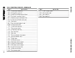
Страница 111: ...rting capacitor resistance A40 1 Start capacitor A40 2 Run capacitor K01 Compressor motor starter relay S01 Main switch S02 Remote control start S10 Fan pressure control switch S11 Safety control switch M01 Compressor motor M10 Fan motor P Compressor motor protector HP Indicates high pressure in the circuit ...

Страница 112: ...PRODUCT USER MANUAL SECTION 3 112 3 53 WIRING DIAGRAM RN250 325 02250195 311 ...

Страница 113: ...ser heater A31 Starting capacitor resistance A40 1 Start capacitor A40 2 Run capacitor K01 Compressor motor starter relay S01 Main switch S02 Remote control start S10 Fan pressure control switch S11 Safety control switch M01 Compressor motor M10 Fan motor P Compressor motor protector HP Indicates high pressure in the circuit ...

Страница 114: ...PRODUCT USER MANUAL SECTION 3 114 3 54 WIRING DIAGRAM RN250 325 230 3 60 A 02250195 973 1 ...

Страница 115: ...1 Main terminal block B15 Control circuit supply EMR4 Phase protection relay F1 F2 F3 EMR4 overload protection F4 A01 primary protection F5 A30 overload protection F13 A01 Secondary protection K01 Compressor contactor K10 Fan contactor M01 Compressor motor M10 Fan motor P01 Thermal protection of compressor P10 Over load protector of fan motor S01 Main switch ...

Страница 116: ...PRODUCT USER MANUAL SECTION 3 116 3 55 WIRING DIAGRAM RN250 325 230 3 60 A 02250195 973 2 ...

Страница 117: ...3 1 Stop button on control panel S03 2 Remote control stop button S10 Fan high pressure control switch S11 High pressure safety control switch S20 Safety thermostat S30 Fan protector A10 1 Running lamp on control panel Green A10 2 Remote control running lamp Green A11 1 Stand by lamp on control panel red A11 2 Remote control Stand by lamp red A20 Drain timer supply EMR4 Phase protection relay AL A...

Страница 118: ...PRODUCT USER MANUAL SECTION 3 118 3 56 WIRING DIAGRAM RN250 325 460 3 60 A 400 3 50 A 02250195 312 1 ...

Страница 119: ...eater B01 Main terminal block B15 Control circuit supply EMR4 Phase protection relay F1 F2 F3 EMR4 overload protection F4 A01 primary protection F5 A30 overload protection F13 A01 Secondary protection K01 Compressor contactor K10 Fan contactor M01 Compressors M10 Fan motor P01 Thermal protection of compressor P10 Over load protector of fan motor S01 Main switch ...

Страница 120: ...PRODUCT USER MANUAL SECTION 3 120 3 57 WIRING DIAGRAM RN250 325 460 3 60 A 400 3 50 A 02250195 312 2 ...

Страница 121: ...f fan S02 1 Start button on control panel S02 2 Remote control start button S03 1 Stop button on control panel S03 2 Remote control stop button S10 Fan high pressure control switch S11 High pressure safety control switch S20 Safety thermostat S30 Fan protector A10 1 Running lamp on control panel Green A10 2 Remote control running lamp Green A11 1 Stand by lamp on control panel red A11 2 Remote con...

Страница 122: ...PRODUCT USER MANUAL SECTION 3 122 3 58 CONTROL CIRCUIT RN250 325 02250195 306 ...

Страница 123: ...y EMR4 Phase protection relay F10 Control circuit protection F11 Drain valve protection K01 Compressor motor relay K10 Fan motor relay K20 Main relay P01 Thermal protection of compressor P10 Thermal protection of fan RL1 ESD2 contact RL2 ESD2 alarm contact S02 1 Start button on control panel S02 2 Remote control start button S03 1 Stop button on control panel S03 2 Remote control stop button S04 R...

Страница 124: ...PRODUCT USER MANUAL SECTION 3 124 3 59 POWER CIRCUIT RN250 325 02250195 306 ...

Страница 125: ...former A30 Compressor chankaser heater B01 Main terminal block EMR4 Phase protection relay F1 F2 A01 Primary protection K01 Compressor contactor 24V K10 Fan contactor 24V K40 Water motor M01 Compressor M10 Fan motor P01 Thermal protection of P10 Overload protector P40 Water motor protection S01 Main switch ...

Страница 126: ...r ant the dryer should be regularly checked to be leak free by qualified refrigerant engineer Refer to section Environmental protection of this manual 3 Every six months check the correct opera tion of the condenser drain trap Replace timer or solenoid valve in case of clogging or malfunctioning 4 Every six months check and clean the drain strainer or the electronic sensor by undoing the access sc...

Страница 127: ...ng drain strainer inside drain ball valve X Cleaning or replacing drain membrane valve 250CFM and larger models X Monitoring working conditions X Table 3 1 Recommended Maintenance Recommended Maintenance Activity Weekly Monthly Semi Annual Annual 5 6 7 9 10 8 11 12 ...

Страница 128: ...temperatures lower than the design conditions Designed conditions and correction fac tors are described in this man ual A high ambient temperature may cause the refrigerant system to operate at higher than normal pressures Results will be higher than normal evaporator tempera ture Important adequate air cir culation around the dryer and proper ventilation in the equip ment room should guarantee a ...

Страница 129: ...ompressor circuit See wiring diagram in chapter rawings of this manual One electrical protection has tripped Reset the protection or replace the blown fuse The dryer is protected against high amp draw by fuse and or overload relay that can trip in case of need Reset or replace fuse once but do not persist if it trips again request assistance from a qualified refrigeration con tractor Dryer on ligh...

Страница 130: ...in have to be checked or replaced every 6 months Sullair zero loss drain has to be cleaned with soft water when needed Bypass system is open Check the valves Important Bypass piping should be installed around the dryer so the dryer can be isolated for ser vice without shutting down the air supply During dryer operation valves must be set so all air goes into the system Check tightness of the bypas...

Страница 131: ...iodically checked and cleaned Shortage of refrigerant Fix the leak and add a charge of refrigerant Loss of refrigerant will cause improper functioning A qualified refrigeration specialist should perform the necessary repairs or factory should be contacted if the units is in warranty Refrigeration system is not functioning Check to be certain refrigerant compressor is running To check if the compre...

Страница 132: ... until frost disappears Allow 15 minutes for pressure stabilization with air flowing Clogged heat exchanger Clean heat exchanger with a reverse air flow Dryer are supposed to be used with compressed air free of any aggressive contaminants Some contamination may require extra maintenance of the heat exchanger Contact your Sullair Distributor The unit will not run or cycles off and on Line disconnec...

Страница 133: ...tem perature Clogged condenser fins Clear fins of all obstructions The clogged fins in the con denser will restrict the air pas sage and reduce the refrigeration capacity causing high tempera ture in the evaporator Fins should be periodically checked and cleaned Shortage of refrigerant Fix the leak and add a charge of refrigerant Loss of refrigerant will cause improper functioning 3 phase dryers a...

Страница 134: ...bar 130 5 174 0 psi 25 bar 362 psi N A N A N A N A 4 sec 5 min N A N A RN 0325 5 10 C 41 50 F 2 05 bar 29 7 psi 9 0 12 0 bar 130 5 174 0 psi 25 bar 362 psi N A N A N A N A 4 sec 5 min N A N A RD 0400 5 10 C 41 50 F 2 05 bar 29 7 psi 9 0 12 0 bar 130 5 174 0 psi 25 bar 362 psi 1 6 bar 23 2 psi 45 C 113 F 4 sec 5 min 11 bar 159 5 psi RD 0500 5 10 C 41 50 F 2 05 bar 29 7 psi 9 0 12 0 bar 130 5 174 0 ...

Страница 135: ...on Cycling 115 1 60 50 0 RN 0050 115 60 A 02250193 814 50 0 2 2 0 67 3 4 NPT F Non Cycling 208 230 1 60 50 0 RN 0050 230 60 A 02250193 838 50 0 2 2 0 67 3 4 NPT F Non Cycling 115 1 60 75 0 RN 0075 115 60 A 02250193 815 75 0 2 4 0 85 3 4 NPT F Non Cycling 208 230 1 60 75 0 RN 0075 230 60 A 02250193 839 75 0 2 4 0 85 3 4 NPT F Non Cycling 115 1 60 100 0 RN 0100 115 60 A 02250193 816 100 0 2 5 0 95 3...

Страница 136: ...ling 460 3 60 500 0 RD 0500 460 60 A 02250193 982 500 0 3 9 2 35 2 NPT F Non Cycling 575 3 60 500 0 RD 0500 575 60 A 02250194 137 500 0 3 9 2 35 2 NPT F Non Cycling 230 3 60 700 0 RD 0700 230 60 A 02250193 851 RD 0700 230 60 W 02250193 861 700 0 3 1 3 45 3 NPT M Non Cycling 460 3 60 700 0 RD 0700 460 60 A 02250193 983 RD 0700 460 60 W 02250194 107 700 0 3 1 3 45 3 NPT M Non Cycling 575 3 60 700 0 ...

Страница 137: ... 02250194 144 RD 2400 575 60 W 02250194 167 2500 0 3 2 9 22 6 FLG Non Cycling 460 3 60 3000 0 RD 3000 460 60 A 02250193 991 RD 3000 460 60 W 02250194 116 3000 0 2 6 12 25 6 FLG Non Cycling 575 3 60 3000 0 RD 3000 575 60 A 02250194 145 RD 3000 575 60 W 02250194 168 3000 0 2 6 12 25 6 FLG Non Cycling 460 3 60 3800 0 RD 3800 460 60 A 02250193 992 RD 3800 460 60 W 02250194 117 3800 0 2 8 14 62 6 FLG N...

Страница 138: ... 3 50 400 0 RD 0400 400 50 A 02250193 917 400 0 3 4 1 92 2 NPT F Non Cycling 400 3 50 500 0 RD 0500 400 50 A 02250193 918 500 0 3 9 2 35 2 NPT F Non Cycling 400 3 50 700 0 RD 0700 400 50 A 02250193 919 RD 0700 400 50 W 02250193 947 700 0 2 5 3 45 3 NPT M Non Cycling 400 3 50 850 0 RD 0850 400 50 A 02250193 920 RD 0850 400 50 W 02250193 948 850 0 2 8 3 64 3 NPT M Non Cycling 400 3 50 1000 0 RD 1000...

Страница 139: ...8 230 1 60 75 0 RN 0075 230 1 60 A 02250193 839 75 0 2 4 0 43 3 4 NPT 15 4 390 28 9 735 17 5 445 124 3 56 5 Non Cycling 115 1 60 100 0 RN 0100 115 1 60 A 02250193 816 100 0 2 5 0 46 3 4 NPT 15 4 390 28 9 735 17 5 445 145 2 66 Non Cycling 208 230 1 60 100 0 RN 0100 230 1 60 A 02250193 841 100 0 2 5 0 46 3 4 NPT 15 4 390 28 9 735 17 5 445 145 2 66 Non Cycling 115 1 60 125 0 RN 0125 115 1 60 A 022501...

Страница 140: ...4 162 850 0 2 4 4 4 3 NPT 31 9 810 58 9 1495 45 9 1166 1100 500 Non Cycling 460 3 60 1000 0 RD 1000 460 3 60 A 02250193 985 RD 1000 460 3 60 W 02250194 109 1000 0 2 8 5 28 3 NPT 31 9 810 73 8 1875 45 9 1166 1122 510 Non Cycling 575 3 60 1000 0 RD 1000 575 3 60 A 02250194 140 RD 1000 575 3 60 W 02250194 163 1000 0 2 8 5 12 3 NPT 31 9 810 73 8 1875 45 9 1166 1122 510 Non Cycling 460 3 60 1250 0 RD 1...

Страница 141: ...00 0 3 5 18 2 8 FLG 45 9 1166 79 9 2030 110 3 2800 2420 1100 Non Cycling 575 3 60 5000 0 RD 5000 575 3 60 A 02250194 147 RD 5000 575 3 60 W 02250194 170 5000 0 3 5 18 8 FLG 45 9 1166 79 9 2030 110 3 2800 2420 1100 Non Cycling 460 3 60 6000 0 RD 6000 460 3 60 A 02250193 994 RD 6000 460 3 60 W 02250194 119 6000 0 3 5 22 27 8 FLG 45 9 1166 79 9 2030 118 1 3000 2750 1250 Non Cycling 575 3 60 6000 0 RD...

Страница 142: ...2250193 917 400 0 3 4 1 92 Non Cycling 400 3 50 500 0 RD 0500 400 3 50 A 02250193 918 500 0 3 9 2 35 Non Cycling 400 3 50 700 0 RD 0700 400 3 50 A 02250193 919 RD 0700 400 3 50 W 02250193 947 700 0 2 5 3 45 Non Cycling 400 3 50 850 0 RD 0850 400 3 50 A 02250193 920 RD 0850 400 3 50 W 02250193 948 850 0 2 8 3 64 Non Cycling DELETE 1000 0 RD 1000 230 3 50 A 1000 0 3 1 3 64 Non Cycling 400 3 50 1000 ...

Страница 143: ...SECTION 3 PRODUCT USER MANUAL 143 ...

Страница 144: ...N A N A N A Flexible steel tube inlet M INL 0015 M INL 0015 M INL 0015 M INL 0015 M INL 0025 Flexible steel tube outlet N A N A N A N A N A Expansion valve M EXV 0075 M EXV 0075 M EXV 0075 M EXV 0075 M EXV 0075 By pass valve N A N A N A N A N A separator N A N A N A N A N A Liquid Receiver N A N A N A N A N A High Pressure Security switch M HPS 0200 M HPS 0200 M HPS 0200 M HPS 0200 M HPS 0200 Fan ...

Страница 145: ...TO 0015 M CTO 0015 M CTO 0015 M CTO 0015 M CTO 0025 Cabinet Base M CBA 0015 M CBA 0015 M CBA 0015 M CBA 0015 M CBA 0025 Cabinette fastener M FAS 1000 M FAS 1000 M FAS 1000 M FAS 1000 M FAS 1000 Cabinette Stud and Nut M STU 1000 M STU 1000 M STU 1000 M STU 1000 M STU 1000 Cabinet handle M CPS 1000 M CPS 1000 M CPS 1000 M CPS 1000 M CPS 1000 Plastic Display cover M PDC 0200 M PDC 0200 M PDC 0200 M P...

Страница 146: ...025 M INL 0050 M INL 0050 M INL 0050 Flexible steel tube outlet N A N A M OTL 0050 M OTL 0050 M OTL 0050 Expansion valve M EXV 0075 M EXV 0075 M EXV 0075 M EXV 0075 M EXV 0075 By pass valve N A N A N A N A N A separator N A N A N A N A N A Liquid Receiver N A N A N A N A N A High Pressure Security switch M HPS 0200 M HPS 0200 M HPS 0200 M HPS 0200 M HPS 0200 Fan on off switch M FNS 0200 M FNS 0200...

Страница 147: ...0 M CTO 0050 M CTO 0050 Cabinet Base M CBA 0025 M CBA 0025 M CBA 0050 M CBA 0050 M CBA 0050 Cabinette fastener M FAS 1000 M FAS 1000 M FAS 1000 M FAS 1000 M FAS 1000 Cabinette Stud and Nut M STU 1000 M STU 1000 M STU 1000 M STU 1000 M STU 1000 Cabinet handle M CPS 1000 M CPS 1000 M CPS 1000 M CPS 1000 M CPS 1000 Plastic Display cover M PDC 0200 M PDC 0200 M PDC 0200 M PDC 0200 M PDC 0200 Cabinet T...

Страница 148: ...NL 0050 M INL 0100 M INL 0100 Flexible steel tube outlet M OTL 0050 M OTL 0050 M OTL 0050 M OTL 0100 M OTL 0100 Expansion valve M EXV 0075 M EXV 0075 M EXV 0075 M EXV 0075 M EXV 0075 By pass valve N A N A N A N A N A separator N A N A N A N A N A Liquid Receiver N A N A N A N A N A High Pressure Security switch M HPS 0200 M HPS 0200 M HPS 0200 M HPS 0200 M HPS 0200 Fan on off switch M FNS 0200 M F...

Страница 149: ... 0050 M CTO 0075 M CTO 0075 Cabinet Base M CBA 0050 M CBA 0050 M CBA 0050 M CBA 0075 M CBA 0075 Cabinette fastener M FAS 1000 M FAS 1000 M FAS 1000 M FAS 1000 M FAS 1000 Cabinette Stud and Nut M STU 1000 M STU 1000 M STU 1000 M STU 1000 M STU 1000 Cabinet handle M CPS 1000 M CPS 1000 M CPS 1000 M CPS 1000 M CPS 1000 Plastic Display cover M PDC 0200 M PDC 0200 M PDC 0200 M PDC 0200 M PDC 0200 Cabin...

Страница 150: ...100 M INL 0100 M INL 0100 M INL 0150 M INL 0150 Flexible steel tube outlet M OTL 0100 M OTL 0100 M OTL 0100 M OTL 0150 M OTL 0150 Expansion valve M EXV 0075 M EXV 0200 M EXV 0200 M EXV 0200 M EXV 0200 By pass valve N A M BYV 0100 M BYV 0100 M BYV 0200 M BYV 0200 separator N A N A N A N A N A Liquid Receiver N A N A N A N A N A High Pressure Security switch M HPS 0200 M HPS 0200 M HPS 0200 M HPS 02...

Страница 151: ... 0100 M CTO 0150 M CTO 0150 Cabinet Base M CBA 0075 M CBA 0100 M CBA 0100 M CBA 0150 M CBA 0150 Cabinette fastener M FAS 1000 M FAS 1000 M FAS 1000 M FAS 1000 M FAS 1000 Cabinette Stud and Nut M STU 1000 M STU 1000 M STU 1000 M STU 1000 M STU 1000 Cabinet handle M CPS 1000 M CPS 1000 M CPS 1000 M CPS 1000 M CPS 1000 Plastic Display cover M PDC 0200 M PDC 0200 M PDC 0200 M PDC 0200 M PDC 0200 Cabin...

Страница 152: ...INL 0150 M INL 0150 M INL 0150 M INL 0200 M INL 0200 Flexible steel tube outlet M OTL 0150 M OTL 0150 M OTL 0150 M OTL 0200 M OTL 0200 Expansion valve M EXV 0200 M EXV 0200 M EXV 0200 M EXV 0200 M EXV 0200 By pass valve M BYV 0200 M BYV 0200 M BYV 0200 M BYV 0200 M BYV 0200 separator N A N A N A N A N A Liquid Receiver N A N A N A N A N A High Pressure Security switch M HPS 0200 M HPS 0200 M HPS 0...

Страница 153: ...CTO 0150 M CTO 0200 M CTO 0200 Cabinet Base M CBA 0150 M CBA 0150 M CBA 0150 M CBA 0200 M CBA 0200 Cabinette fastener M FAS 1000 M FAS 1000 M FAS 1000 M FAS 1000 M FAS 1000 Cabinette Stud and Nut M STU 1000 M STU 1000 M STU 1000 M STU 1000 M STU 1000 Cabinet handle M CPS 1000 M CPS 1000 M CPS 1000 M CPS 1000 M CPS 1000 Plastic Display cover M PDC 0200 M PDC 0200 M PDC 0200 M PDC 0200 M PDC 0200 Ca...

Страница 154: ...tube outlet M OTL 0200 M OTL 0200 N A N A N A Expansion valve M EXV 0200 M EXV 0200 M EXV 0850 M EXV 0850 M EXV 0850 By pass valve M BYV 0200 M BYV 0200 M BYV 1000 M BYV 1000 M BYV 1000 separator N A N A N A N A N A Liquid Receiver N A N A M RCV 0850 M RCV 0850 M RCV 0850 High Pressure Security switch M HPS 0200 M HPS 0200 M HPS 1000 M HPS 1000 M HPS 1000 Fan on off switch M FNS 0200 M FNS 0200 M ...

Страница 155: ...0400 M CRE 0400 M CRE 0400 Cabinet Top M CTO 0200 M CTO 0200 M CTO 0400 M CTO 0400 M CTO 0400 Cabinet Base M CBA 0200 M CBA 0200 M CBA 0400 M CBA 0400 M CBA 0400 Cabinette fastener M FAS 1000 M FAS 1000 M FAS 1000 M FAS 1000 M FAS 1000 Cabinette Stud and Nut M STU 1000 M STU 1000 M STU 1000 M STU 1000 M STU 1000 Cabinet handle M CPS 1000 M CPS 1000 M CPS 1000 M CPS 1000 M CPS 1000 Plastic Display ...

Страница 156: ...M EXV 1000 M EXV 1000 TN2 No 4 By pass valve M BYV 1000 M BYV 1000 M BYV 1000 M BYV 1000 M BYV 1000 M BYV 1000 separator N A N A N A N A N A N A Liquid Receiver M RCV 0850 M RCV 0850 M RCV 0850 M RCV 0850 M RCV 0850 M RCV 0850 High Pressure Security switch M HPS 1000 M HPS 1000 M HPS 1000 M HPS 1000 M HPS 1000 M HPS 1000 Fan on off switch M FNS 0400 M FNS 0400 M FNS 0400 M FNS 0400 M FNS 0400 M FN...

Страница 157: ... M CRI 0400 M CRI 0400 M CRI 0400 Cabinet Rear M CRE 0400 M CRE 0400 M CRE 0400 M CRE 0400 M CRE 0400 M CRE 0400 Cabinet Top M CTO 0400 M CTO 0400 M CTO 0400 M CTO 0400 M CTO 0400 M CTO 0400 Cabinet Base M CBA 0400 M CBA 0400 M CBA 0400 M CBA 0400 M CBA 0400 M CBA 0400 Cabinette fastener M FAS 1000 M FAS 1000 M FAS 1000 M FAS 1000 M FAS 1000 M FAS 1000 Cabinette Stud and Nut M STU 1000 M STU 1000 ...

Страница 158: ...158 NOTES ...

Страница 159: ...85 communication interface that can be used for remotely monitoring channel temperatures set points input and output states Modbus RTU protocol is used for communication The front panel of the controller contains a four line 20 character LCD display and 10 buttons that are used in configuration and manual control operations The dimensions of the controller are 96 x 192 mm front panel with a depth ...

Страница 160: ...f E 680 Controller TERMINALS IN THE UPPER ROW These terminals are used for temperature sensors Pt 100 Spare channels are measured by the controller but can not be monitored and sensor break for these channels has no effect on the operation of the controller TERMINALS IN THE MIDDLE ROW These terminals are used for digital outputs and digital inputs The names and the functions in the order of the te...

Страница 161: ...ed to the dryer in 8 different screens While one screen is displayed pressing button reverts to the normal operation screen The views of the screens in sequence of the appearance are shown below 9 COMM For D Out 5 8 10 D OUTPUT 5 Drain Output Inverted 11 D OUTPUT 6 Spare 12 D OUTPUT 7 Spare 13 D OUTPUT 8 Alarm Output Horn 14 15 COMM For D INPUTS 16 COMM For D INPUTS 17 COMM For D INPUTS 18 D INPUT...

Страница 162: ...EMP 18 C AMBIENT TEMPERATURE 19 C AUXILIARY TEMP 18 C COMPRESSOR OK FAN MOTOR OK PHASE SEQUENCE OK REMOTE CONTROL OK TOTAL TIME 22 2 ECO TIME 8 1 RUN TIME 22 2 FILTER TIME 22 2 1 REMOTE DISABLE 2 INLET AIR TEMP HI 3 EXCH TEMP LO 4 COMPRESSOR FAULT DATE 22 03 10 TIME 12 30 45 DAY MONDAY D INPUT1 LLLLLLLL D INPUT2 LLLLLLLL D OUTPUT LLLHHLLL ...

Страница 163: ...d states respectively In order to start the dryer all the temperatures except the exchanger temperature must be between their low and high limits The low pressure line temperature can be HIGH Digital inputs 3 to 8 should not be activated If this is not the case instead of READY message DISABLED message is displayed in the normal operation screen When the dryer is started the normal operation scree...

Страница 164: ...arameters Page The factory setting of the security code is 10 The Configuration Pages and the parameters in the configuration pages are given below GENERAL PARAMETERS PAGE 1 Language 2 Communication Address 3 Baud Rate 4 Parity 5 Message Text 6 Security Code TEMPERATURE SET POINTS PAGE FACTORY SETTINGS 1 Inlet Air Temp Low Alarm Setpoint 32 F 0 C 2 Inlet Air Temp High Alarm Setpoint 131 F 55 C 3 E...

Страница 165: ...ent Temp Cal Channel 1 4 1 RT Cal 390 ohm 5 2 RT Cal 390 ohm 6 3 RT Cal 390 ohm 7 4 RT Cal 390 ohm 8 5 RT Cal 390 ohm 9 6 RT Cal 390 ohm 10 7 RT Cal 390 ohm 11 8 RT Cal 390 ohm The 7th and 8th Parameters in the Time Parameters Page Filter Change Period and Maintenance Period and all the parameters in Calibration Page can not be edited unless the Digital Input 10 is activated Configuration Enable W...

Страница 166: ...E 680 CONTROLLER FOR REFRIGERANT DRYERS SECTION 4 166 4 3 ED RD400 02250195 264 R00 ...

Страница 167: ...M MMV 3000 MEMBRANE VALVE 1 16 M MMM 3000 MEMBRANE 1 17 M CFR 0400 CABINET FRONT 1 18 M CSI 0400 CABINET SIDE 2 19 M CRE 0400 CABINET REAR 1 20 M CTO 0400 CABINET TOP 1 21 M CBA 0400 CABINET BASE 1 22 M CBL 0400 CABINET LEG 4 23 M HP1 0400 CABINETHORIZONTAL PROFILE 1 2 24 M HP2 0400 CABINET HORIZONTAL PROFILE 2 2 25 M CTC 3000 CABINET TOP CORNER 4 26 M CPS 3000 CABINET HANDLE 8 27 M STU 3000 CABIN...

Страница 168: ...E 680 CONTROLLER FOR REFRIGERANT DRYERS SECTION 4 168 4 4 ED RD500 02250195 266 R00 ...

Страница 169: ...D VALVE 1 16 M MMV 3000 MEMBRANE VALVE 1 17 M MMM 3000 MEMBRANE 1 18 M CFR 0850 CABINET FRONT 1 19 M CSI 0850 CABINET SIDE 2 20 M CRE 0850 CABINET REAR 1 21 M CTO 0700 CABINET TOP 1 22 M CBA 0850 CABINET BASE 1 23 M CBL 0850 CABINET LEG 4 24 M HP1 0850 CABINETHORIZONTAL PROFILE 1 2 25 M HP2 0850 CABINET HORIZONTAL PROFILE 2 2 26 M CTC 3000 CABINET TOP CORNER 4 27 M CPS 3000 CABINET HANDLE 8 28 M S...

Страница 170: ...E 680 CONTROLLER FOR REFRIGERANT DRYERS SECTION 4 170 4 5 ED RD700 02250195 266 R00 ...

Страница 171: ...D VALVE 1 16 M MMV 3000 MEMBRANE VALVE 1 17 M MMM 3000 MEMBRANE 1 18 M CFR 0850 CABINET FRONT 1 19 M CSI 0850 CABINET SIDE 2 20 M CRE 0850 CABINET REAR 1 21 M CTO 0700 CABINET TOP 1 22 M CBA 0850 CABINET BASE 1 23 M CBL 0850 CABINET LEG 4 24 M HP1 0850 CABINETHORIZONTAL PROFILE 1 2 25 M HP2 0850 CABINET HORIZONTAL PROFILE 2 2 26 M CTC 3000 CABINET TOP CORNER 4 27 M CPS 3000 CABINET HANDLE 8 28 M S...

Страница 172: ...E 680 CONTROLLER FOR REFRIGERANT DRYERS SECTION 4 172 4 6 ED RD700 AIR COOLED 02250196 590 R00 ...

Страница 173: ...SSEMBLY 1 4 M DRI 1200 DRIER DEHYDRATOR 1 5 M EXC 0200 HEAT EXCHANGER 3 6 M EXV 0700 EXPANSION VALVE 1 7 M BYV 1200 BYPASS VALVE 1 8 M SPR 2000 SEPARATOR 1 9 M RCV 0850 LIQUID RECEIVER 1 10 M HPS 6000 HIGH PRESSURE SECURITY SWITCH 1 11 M FNS 0400 FAN ON OFF SWITCH 2 12 M LPS 6000 LOW PRESSURE SWITCH 1 13 M MKP 6000 MIKROPROCESSOR 1 14 M MNS 0700 MAIN SWITCH 1 15 M SLV 6000 24 SELENOID VALVE 1 16 M...

Страница 174: ...E 680 CONTROLLER FOR REFRIGERANT DRYERS SECTION 4 174 4 7 ED RD850 02250195 266 R00 ...

Страница 175: ...D VALVE 1 16 M MMV 1000 MEMBRANE VALVE 1 17 M MMM 1000 MEMBRANE 1 18 M CFR 0850 CABINET FRONT 1 19 M CSI 0850 CABINET SIDE 2 20 M CRE 0850 CABINET REAR 1 21 M CTO 0850 CABINET TOP 1 22 M CBA 0850 CABINET BASE 1 23 M CBL 0850 CABINET LEG 4 24 M HP1 0850 CABINETHORIZONTAL PROFILE 1 2 25 M HP2 0850 CABINET HORIZONTAL PROFILE 2 2 26 M CTC 3000 CABINET TOP CORNER 4 27 M CPS 3000 CABINET HANDLE 8 28 M S...

Страница 176: ...E 680 CONTROLLER FOR REFRIGERANT DRYERS SECTION 4 176 4 8 ED RD850 AIR COOLED 02250196 591 R00 ...

Страница 177: ...200 HEAT EXCHANGER 4 6 M EXV 0850 EXPANSION VALVE 2 7 M BYV 1200 BYPASS VALVE 1 8 M SPR 2000 SEPARATOR 1 9 M RCV 0850 LIQUID RECEIVER 1 10 M HPS 6000 HIGH PRESSURE SECURITY SWITCH 1 11 M FNS 0400 FAN ON OFF SWITCH 2 12 M LPS 6000 LOW PRESSURE SWITCH 1 13 M MKP 6000 MIKROPROCESSOR 1 14 M MNS 1600 MAIN SWITCH 1 15 M SLV 6000 24 SELENOID VALVE 1 16 M MMV 6000 MEMBRANE VALVE 1 17 M MMM 6000 MEMBRANE 1...

Страница 178: ...E 680 CONTROLLER FOR REFRIGERANT DRYERS SECTION 4 178 4 9 ED RD1000 02250195 266 R00 ...

Страница 179: ...ID VALVE 1 16 M MMV 1000 MEMBRANE VALVE 1 17 M MMM 1000 MEMBRANE 1 18 M CFR 1000 CABINET FRONT 1 19 M CSI 1000 CABINET SIDE 2 20 M CRE 1000 CABINET REAR 1 21 M CTO 1000 CABINET TOP 1 22 M CBA 1000 CABINET BASE 1 23 M CBL 1000 CABINET LEG 4 24 M HP1 1000 CABINETHORIZONTAL PROFILE 1 2 25 M HP2 1000 CABINET HORIZONTAL PROFILE 2 2 26 M CTC 3000 CABINET TOP CORNER 4 27 M CPS 3000 CABINET HANDLE 8 28 M ...

Страница 180: ...E 680 CONTROLLER FOR REFRIGERANT DRYERS SECTION 4 180 4 10 ED RD1000 AIR COOLED 02250196 592 R00 ...

Страница 181: ...00 HIGH PRESSURE SECURITY SWITCH 1 11 M FNS 0400 FAN ON OFF SWITCH 2 12 M LPS 6000 LOW PRESSURE SWITCH 1 13 M MKP 6000 MIKROPROSESSOR 1 14 M MNS 1600 MAIN SWITCH 1 15 M SLV 6000 24 SELENOID VALVE 1 16 M MMV 6000 MEMBRANE VALVE 1 17 M MMM 6000 MEMBRANE 1 18 M CFR 1000 CABINET FRONT 1 19 M CSI 1000 CABINET SIDE 2 20 M CRE 1000 CABINET REAR 1 21 M CTO 1000 CABINET TOP 1 22 M CBA 1000 CABINET BASE 1 2...

Страница 182: ...E 680 CONTROLLER FOR REFRIGERANT DRYERS SECTION 4 182 4 11 ED RD1200 AIR COOLED 02250196 593 R00 ...

Страница 183: ...11 M FNS 0400 FAN ON OFF SWITCH 2 12 M LPS 6000 LOW PRESSURE SWITCH 1 13 M MKP 6000 MIKROPROSESSOR 1 14 M MNS 1600 MAIN SWITCH 1 15 M SLV 6000 24 SELENOID VALVE 1 16 M MMV 6000 MEMBRANE VALVE 1 17 M MMM 6000 MEMBRANE 1 18 M CFR 1000 CABINET FRONT 1 19 M CSI 1000 CABINET SIDE 2 20 M CRE 1000 CABINET REAR 1 21 M CTO 1000 CABINET TOP 1 22 M CBA 1000 CABINET BASE 1 23 M CBL 1200 CABINET LEG 4 24 M HP1...

Страница 184: ...E 680 CONTROLLER FOR REFRIGERANT DRYERS SECTION 4 184 4 12 ED RD1600 AIR COOLED 02250196 594 R00 ...

Страница 185: ...WITCH 1 11 M FNS 0400 FAN ON OFF SWITCH 2 12 M LPS 6000 LOW PRESSURE SWITCH 1 13 M MKP 6000 MIKROPROSESSOR 1 14 M MNS 1600 MAIN SWITCH 1 15 M SLV 6000 24 SELENOID VALVE 1 16 M MMV 6000 MEMBRANE VALVE 1 17 M MMM 6000 MEMBRANE 1 18 M CFR 6000 CABINET FRONT 1 19 M CSI 6000 CABINET SIDE 2 20 M CRE 6000 CABINET REAR 1 21 M CTO 6000 CABINET TOP 1 22 M CBA 6000 CABINET BASE 1 23 M CBL 6000 CABINET LEG 4 ...

Страница 186: ...E 680 CONTROLLER FOR REFRIGERANT DRYERS SECTION 4 186 4 13 ED RD2000 AIR COOLED 02250196 595 R00 ...

Страница 187: ... 2 12 M LPS 6000 LOW PRESSURE SWITCH 1 13 M MKP 6000 MIKROPROSESSOR 1 14 M MNS 3000 MAIN SWITCH 1 15 M SLV 6000 24 SELENOID VALVE 1 16 M MMV 6000 MEMBRANE VALVE 1 17 M MMM 6000 MEMBRANE 1 18 M CFR 2000 CABINET FRONT 1 19 M CSI 2000 CABINET SIDE 2 20 M CRE 2000 CABINET REAR 1 21 M CTO 2000 CABINET TOP 1 22 M CBA 2000 CABINET BASE 1 23 M CBL 2000 CABINET LEG 4 24 M HP1 2000 CABINET HORIZONTAL PROFIL...

Страница 188: ...E 680 CONTROLLER FOR REFRIGERANT DRYERS SECTION 4 188 4 14 ED RD2400 AIR COOLED 02250196 596 R00 ...

Страница 189: ... 2 12 M LPS 6000 LOW PRESSURE SWITCH 1 13 M MKP 6000 MIKROPROSESSOR 1 14 M MNS 3000 MAIN SWITCH 1 15 M SLV 6000 24 SELENOID VALVE 1 16 M MMV 6000 MEMBRANE VALVE 1 17 M MMM 6000 MEMBRANE 1 18 M CFR 2400 CABINET FRONT 1 19 M CSI 2400 CABINET SIDE 2 20 M CRE 2400 CABINET REAR 1 21 M CTO 2400 CABINET TOP 1 22 M CBA 2400 CABINET BASE 1 23 M CBL 2400 CABINET LEG 4 24 M HP1 2400 CABINET HORIZONTAL PROFIL...

Страница 190: ...E 680 CONTROLLER FOR REFRIGERANT DRYERS SECTION 4 190 4 15 ED RD3000 AIR COOLED 02250196 597 R00 ...

Страница 191: ... 2 12 M LPS 6000 LOW PRESSURE SWITCH 1 13 M MKP 6000 MIKROPROSESSOR 1 14 M MNS 3000 MAIN SWITCH 1 15 M SLV 6000 24 SELENOID VALVE 1 16 M MMV 6000 MEMBRANE VALVE 1 17 M MMM 6000 MEMBRANE 1 18 M CFR 3000 CABINET FRONT 1 19 M CSI 3000 CABINET SIDE 2 20 M CRE 3000 CABINET REAR 1 21 M CTO 3000 CABINET TOP 1 22 M CBA 3000 CABINET BASE 1 23 M CBL 6000 CABINET LEG 4 24 M HP1 3000 CABINET HORIZONTAL PROFIL...

Страница 192: ...E 680 CONTROLLER FOR REFRIGERANT DRYERS SECTION 4 192 4 16 ED RD3800 AIR COOLED 02250196 598 R00 ...

Страница 193: ...W PRESSURE SWITCH 2 13 M MKP 6000 MIKROPROSESSOR 1 14 M MNS 6000 MAIN SWITCH 1 15 M SLV 6000 24 SELENOID VALVE 1 16 M MMV 6000 MEMBRANE VALVE 1 17 M MMM 6000 MEMEBRANE 1 18 M CFR 3800 CABINET FRONT 1 19 M SCI 3800 CABIENT SIDE LEFT 1 20 M SCI 3800 CABINET SIDE RIGHT 1 21 M CRE 3800 CABINET REAR 1 22 M CTO 3800 CABINET TOP 1 23 M CBA 3800 CABINET BASE 1 24 M CBL 6000 CABINET LEG 4 25 M HP1 3800 CAB...

Страница 194: ...SECTION 4 E 680 CONTROLLER FOR REFRIGERANT DRYERS 194 4 17 ED RD5000 AIR COOLED 02250196 599 R00 ...

Страница 195: ...OW PRESSURE SWITCH 1 13 M MKP 6000 MIKROPROSESSOR 1 14 M MNS 6000 MAIN SWITCH 1 15 M SLV 6000 24 SELENOID VALVE 1 16 M MMV 6000 MEMBRANE VALVE 1 17 M MMM 6000 MEMBRANE 1 18 M CFR 5000 CABINET FRONT 1 19 M CSI 5000 CABINET SIDE LEFT 1 20 M CSI 5000 CABINET SIDE RIGHT 1 21 M CRE 5000 CABINET REAR 1 22 M CTO 5000 CABINET TOP 1 23 M CBA 5000 CABINET BASE 1 24 M CBL 6000 CABINET LEG 4 25 M HP1 5000 CAB...

Страница 196: ...E 680 CONTROLLER FOR REFRIGERANT DRYERS SECTION 4 196 4 18 ED RD6000 AIR COOLED 02250196 600 R00 ...

Страница 197: ... 3 12 M LPS 6000 LOW PRESSURE SWITCH 1 13 M MKP 6000 MIKROPROSESSOR 1 14 M MNS 6000 MAIN SWITCH 1 15 M SLV 6000 24 SELENOID VALVE 1 16 M MMV 6000 MEMBRANE VALVE 1 17 M MMM 6000 MEMBRANE 1 18 M CFR 6000 CABINET FRONT 1 19 M CSI 6000 CABINET SIDE 2 20 M CRE 6000 CABINET REAR 1 21 5 CTO 6000 CABINET TOP 1 22 M CBA 6000 CABINET BASE 1 23 M CBL 6000 CABINET LEG 4 24 M HP1 6000 CABINET HORIZONTAL PROFIL...

Страница 198: ...SECTION 4 E 680 CONTROLLER FOR REFRIGERANT DRYERS 198 4 19 ID RD400 02250195 264 ...

Страница 199: ...SECTION 4 E 680 CONTROLLER FOR REFRIGERANT DRYERS 199 ...

Страница 200: ...E 680 CONTROLLER FOR REFRIGERANT DRYERS SECTION 4 200 4 20 ID RD500 850 02250195 266 ...

Страница 201: ...93 983 460V 3Ph 60Hz AIR COOLED RD700 02250193 138 575V 3Ph 60Hz AIR COOLED RD700 02250193 920 400V 3Ph 50Hz AIR COOLED RD850 02250193 852 230V 3Ph 60Hz AIR COOLED RD850 02250193 984 460V 3Ph 60Hz AIR COOLED RD850 02550193 139 575V 3Ph 60Hz AIR COOLED RD850 WITHOUT PALLET SIZE WITH PALLETT SIZE GROSS WEIGHT NET WEIGHT DRYER 29 33 33 27 50 745mm 845mm 1270mm 34 25 48 43 59 45 870mm 1230mm 1510mm 80...

Страница 202: ...E 680 CONTROLLER FOR REFRIGERANT DRYERS SECTION 4 202 4 21 ID RD1000 1200 AIR COOLED 02250195 267 ...

Страница 203: ...3Ph 60Hz AIR COOLED RD1000 022501934 140 575V 3Ph 60Hz AIR COOLED RD1000 02250193 922 400V 3Ph 50Hz AIR COOLED RD1200 02250193 986 460V 3Ph 60Hz AIR COOLED RD1200 02250194 141 575V 3Ph 60Hz AIR COOLED RD1200 WITHOUT PALLET SIZE WITH PALLETT SIZE GROSS WEIGHT NET WEIGHT DRYER 31 89 45 87 74 2 810mm 1165mm 1885mm 37 52 28 82 68 940mm 1300mm 2100mm 1483 LB 1230 LB RD 1200 1389 LB 1146 LB RD 1000 ...

Страница 204: ...E 680 CONTROLLER FOR REFRIGERANT DRYERS SECTION 4 204 4 22 ID RD1000 1200 WATER COOLED 02250195 267 ...

Страница 205: ...h 60Hz WATER COOLED RD1000 02250194 163 575V 3Ph 60Hz WATER COOLED RD1000 02250193 950 400V 3Ph 50Hz WATER COOLED RD1200 02250194 110 460V 3Ph 60Hz WATER COOLED RD1200 02250194 164 575V 3Ph 60Hz WATER COOLED RD1200 WITHOUT PALLET SIZE WITH PALLETT SIZE GROSS WEIGHT NET WEIGHT DRYER 31 89 45 87 74 2 810mm 1165mm 1885mm 37 51 18 82 68 940mm 1300mm 2100mm 1483 LB 1230 LB RD 1200 1389 LB 1146 LB RD 10...

Страница 206: ...E 680 CONTROLLER FOR REFRIGERANT DRYERS SECTION 4 206 4 23 ID RD1600 2000 AIR COOLED 02250195 268 ...

Страница 207: ...ER POWER RATINGS COOLING DECAL 02250193 923 400V 3Ph 50Hz AIR COOLED RD1600 02250193 988 460V 3Ph 60Hz AIR COOLED RD1600 02250194 142 575V 3Ph 60Hz AIR COOLED RD1600 02250193 924 400V 3Ph 50Hz AIR COOLED RD2000 02250193 989 460V 3Ph 60Hz AIR COOLED RD2000 02250194 143 575V 3Ph 60Hz AIR COOLED RD2000 ...

Страница 208: ...E 680 CONTROLLER FOR REFRIGERANT DRYERS SECTION 4 208 4 24 ID RD1600 2000 WATER COOLED 02250195 268 ...

Страница 209: ...OWER RATINGS COOLING DECAL 02250193 951 400V 3Ph 50Hz WATER COOLED RD1600 02250194 113 460V 3Ph 60Hz WATER COOLED RD1600 02250194 165 575V 3Ph 60Hz WATER COOLED RD1600 02250193 953 400V 3Ph 50Hz WATER COOLED RD2000 02250194 114 460V 3Ph 60Hz WATER COOLED RD2000 02250194 166 575V 3Ph 60Hz WATER COOLED RD2000 ...

Страница 210: ...E 680 CONTROLLER FOR REFRIGERANT DRYERS SECTION 4 210 4 25 ID RD2400 3000 AIR COOLED 02250195 269 ...

Страница 211: ...BER POWER RATINGS COOLING DECAL 02250193 925 400V 3Ph 50Hz AIR COOLED RD2400 02250193 990 460V 3Ph 60Hz AIR COOLED RD2400 02250194 144 575V 3Ph 60Hz AIR COOLED RD2400 02250193 926 400V 3Ph 50Hz AIR COOLED RD3000 02250193 991 460V 3Ph 60Hz AIR COOLED RD3000 02250194 145 575V 3Ph 60Hz AIR COOLED RD3000 ...

Страница 212: ...E 680 CONTROLLER FOR REFRIGERANT DRYERS SECTION 4 212 4 26 ID RD2400 3000 WATER COOLED 02250195 269 ...

Страница 213: ...OWER RATINGS COOLING DECAL 02250193 954 400V 3Ph 50Hz WATER COOLED RD2400 02250194 115 460V 3Ph 60Hz WATER COOLED RD2400 02250194 167 575V 3Ph 60Hz WATER COOLED RD2400 02250193 955 400V 3Ph 50Hz WATER COOLED RD3000 02250194 116 460V 3Ph 60Hz WATER COOLED RD3000 02250194 168 575V 3Ph 60Hz WATER COOLED RD3000 ...

Страница 214: ...E 680 CONTROLLER FOR REFRIGERANT DRYERS SECTION 4 214 4 27 ID RD3800 AIR COOLED 02250195 270 ...

Страница 215: ...R REFRIGERANT DRYERS 215 4 27 ID RD3800 AIR COOLED DRYER PART NUMBER POWER RATINGS COOLING DECAL 02250193 927 400V 3Ph 50Hz AIR COOLED RD3800 02250193 992 460V 3Ph 60Hz AIR COOLED RD3800 02250194 146 575V 3Ph 60Hz AIR COOLED RD3800 ...

Страница 216: ...E 680 CONTROLLER FOR REFRIGERANT DRYERS SECTION 4 216 4 28 ID RD3800 WATER COOLED 02250195 270 ...

Страница 217: ...FRIGERANT DRYERS 217 4 28 ID RD3800 WATER COOLED DRYER PART NUMBER POWER RATINGS COOLING DECAL 02250193 956 400V 3Ph 50Hz WATER COOLED RD3800 02250194 117 460V 3Ph 60Hz WATER COOLED RD3800 02250194 169 575V 3Ph 60Hz WATER COOLED RD3800 ...

Страница 218: ...E 680 CONTROLLER FOR REFRIGERANT DRYERS SECTION 4 218 4 29 P I RD400 02250195 291 ...

Страница 219: ...ESSOR 2 REFRIGERANT CONDENSER 3 FAN MOTOR 4 FAN MOTOR SWITCH 5 EVAPORATOR 6 AIR AIR EXCHANGER 7 PRESSURE REGULATOR 8 DEHYDRATOR 9 DEW POINT INDICATOR 10 BY PASS VALVE 11 LIQUID RECEIVER NOTE MARK TAG COMPONENT CONTAINER WITH SULLAIR P N AND REVISION MODEL REFRIGERANT TYPE LB RD400 R134A 6 613 ...

Страница 220: ...E 680 CONTROLLER FOR REFRIGERANT DRYERS SECTION 4 220 4 30 P I RD500 850 02250195 293 ...

Страница 221: ...CONDENSER 3 FAN MOTOR 4 FAN MOTOR SWITCH 5 EVAPORATOR 6 AIR AIR EXCHANGER 7 PRESSURE REGULATOR 8 DEHYDRATOR 9 DEW POINT INDICATOR 10 BY PASS VALVE 11 LIQUID RECEIVER 12 LIQUID SEPARATOR NOTE MARK TAG COMPONENT CONTAINER WITH SULLAIR P N AND REVISION MODEL REFRIGERANT TYPE LB RD500 R134A 8 818 RD700 9 369 RD850 11 023 ...

Страница 222: ...E 680 CONTROLLER FOR REFRIGERANT DRYERS SECTION 4 222 4 31 P I RD700 850 02250195 294 ...

Страница 223: ...COMPRESSOR 2 WATER CONDENSER 3 EVAPORATOR 4 AIR AIR EXCHANGER 5 PRESSURE REGULATOR 6 DEHYDRATOR 7 DEW POINT INDICATOR 8 BY PASS VALVE 9 LIQUID RECEIVER 10 LIQUID SEPARATOR NOTE MARK TAG COMPONENT CONTAINER WITH SULLAIR P N AND REVISION MODEL REFRIGERANT TYPE LB RD700 R134A 9 369 RD850 11 023 ...

Страница 224: ...E 680 CONTROLLER FOR REFRIGERANT DRYERS SECTION 4 224 4 32 P I RD1000 6000 02250195 297 ...

Страница 225: ...NDENSER 3 FAN MOTOR 4 FAN MOTOR SWITCH 5 DEHYDRATOR 6 BY PASS VALVE 7 LIQUID RECEIVER 8 LIQUID SEPARATOR 9 PRESSURE REGULATOR 10 ALUMINIUM BRAZED PLATE HEAT EXCHANGER NOTE MARK TAG COMPONENT CONTAINER WITH SULLAIR P N AND REVISION MODEL REFRIGERANT TYPE RD1000 R134A RD1200 RD1600 RD2000 RD2400 RD3000 RD3800 RD5000 RD6000 ...

Страница 226: ...E 680 CONTROLLER FOR REFRIGERANT DRYERS SECTION 4 226 4 33 P I RD1000 6000 02250195 298 ...

Страница 227: ...OR 2 WATER CONDENSER 3 DEHYDRATOR 4 BY PASS VALVE 5 LIQUID RECEIVER 6 LIQUID SEPARATOR 7 PRESSURE REGULATOR 8 ALUMINIUM BRAZED PLATE HEAT EXCHANGER NOTE MARK TAG COMPONENT CONTAINER WITH SULLAIR P N AND REVISION MODEL REFRIGERANT TYPE RD1000 R134A RD1200 RD1600 RD2000 RD2400 RD3000 RD3800 RD5000 RD6000 ...

Страница 228: ...E 680 CONTROLLER FOR REFRIGERANT DRYERS SECTION 4 228 4 34 WIRING DIAGRAM RD400 230 3 60 A 02250195 313 1 ...

Страница 229: ...er A30 Compressor chankaser heater B01 Main terminal block B15 Control circuit supply EMR4 Phase protection relay F1 F2 F3 A01 Primary protection F13 Control circuit protection K01 Compressor contactor 24V K10 Fan contactor 24V M01 Compressors M10 Fan motor P01 Thermal protection off on compressor P10 Over load protector S01 Main switch ...

Страница 230: ...E 680 CONTROLLER FOR REFRIGERANT DRYERS SECTION 4 230 4 35 WIRING DIAGRAM RD400 230 3 60 A 02250195 313 2 ...

Страница 231: ...r Manual On off S05 Remote Control Contact S06 Service Contact S10 Fan Pressure Switch S11 High Pressure Security Control 2 S12 Low Pressure Security Control 1 K01 Compressor Motor Relay K10 Fan Motor Relay A10 Remote Control Running Lamp Green A11 Remote Control Stand by Lamp Red A20 Electronic Timer Supply A41 Remote Control Alarm Contact PT1 Inlet Air Temperature Sensor Pt100 PT2 Heat Exchanger...

Страница 232: ...E 680 CONTROLLER FOR REFRIGERANT DRYERS SECTION 4 232 4 36 WIRING DIAGRAM RD400 460 3 60 A 400 3 50 A 02250195 974 1 ...

Страница 233: ...hankaser Heaters B01 Main Terminal Block B15 Control Circuit Supply EMR4 Phase Protection Relay F1 F2 F3 Emr4 Poverload Protection F4 A01 Primary Protection F5 A40 Overload Protection F13 Control Circuit Protection K01 Compressor Contactor 24v M01 Compressor Motor M10 Fan Motor P01 Thermal Protection Off on Compressor P10 Fan Motor Over Load Protector S01 Main Switch ...

Страница 234: ...E 680 CONTROLLER FOR REFRIGERANT DRYERS SECTION 4 234 4 37 WIRING DIAGRAM RD400 460 3 60 A 400 3 50 A 02250195 974 2 ...

Страница 235: ...Contact S10 Fan Pressure Switch S11 2 High Pressure Security Control 2 S11 1 Low Pressure Security Control 1 K01 Compressor Motor Relay K10 Fan Motor Relay A10 Remote Control Running Lamp Green A11 Remote Control Stand by Lamp Red A20 Electronic Timer Supply A41 Remote Control Alarm Contact PT1 Inlet Air Temperature Sensor Pt100 PT2 Heat Exchanger Temperature Sensor Pt100 PT3 Low Pressure Line Sen...

Страница 236: ...E 680 CONTROLLER FOR REFRIGERANT DRYERS SECTION 4 236 4 38 WIRING DIAGRAM RD500 700 230 3 60 A 02250195 975 1 ...

Страница 237: ... B15 Control Circuit Supply EMR4 Phase Protection Relay F1 F2 F3 Emr4 Poverload Protection F4 A01 Rimary Protection F5 A30 Overload Protection F13 Control Circuit Protection K01 1 Compressor Contactor 24v K01 2 Compressor Contactor 24v K10 Fan Contactor 24v M01 Compressor Motor M10 1 Fan Motor M10 2 Fan Motor P01 Thermal Protection Off on Compressor P10 Fan Motor Over Load Protector S01 Main Switc...

Страница 238: ...E 680 CONTROLLER FOR REFRIGERANT DRYERS SECTION 4 238 4 39 WIRING DIAGRAM RD500 700 230 3 60 A 02250195 975 2 ...

Страница 239: ...S10 1 Fan Pressure Switch 1 S10 2 Fan Pressure Switch 2 S11 1 Low Pressure Security Control 1 S11 2 High Pressure Security Control 2 K01 Compressor Motor Relay K10 1 Ran Motor Relay 1 K10 2 Fan Motor Relay 2 A20 Electronic Timer Supply A10 Remote Control Running Lamp Green A11 Remote Control Stand by Lamp Red_ A41 Remote Control Alarm Contact PT1 Inlet Air Temperature Sensor Pt100 PT2 Heat Exchang...

Страница 240: ...E 680 CONTROLLER FOR REFRIGERANT DRYERS SECTION 4 240 4 40 WIRING DIAGRAM RD 500 700 850 1000 1200 1600 2000 2400 3000 3800 5000 6000 460 3 60 A 400 3 50 A 02250195 314 1 ...

Страница 241: ...ankaser heater B01 Main terminal block B15 Control circuit supply EMR4 Phase protection relay F1 F2 F3 EMR4 Poverload Protection F4 A01 Primary Protection F5 A30 Overload Protection F13 Control circuit protection K01 1 Compressor contactor 24V K01 2 Compressor contactor 24V K10 Fan contactor 24V M01 Compressor M10 1 Fan motor M10 2 Fan motor P01 Thermal protection off on compressor P10 Over load p...

Страница 242: ...E 680 CONTROLLER FOR REFRIGERANT DRYERS SECTION 4 242 4 41 WIRING DIAGRAM RD 500 700 850 1000 1200 1600 2000 2400 3000 3800 5000 6000 460 3 60 A 400 3 50 A 02250195 314 2 ...

Страница 243: ...ual On 0ff S06 Service Contact S10 1 Fan Pressure Switch 1 S10 2 Fan Pressure Switch 2 S11 1 Low Pressure Security Control 1 S11 2 High Pressure Security Control 2 K01 Compressor Motor Relay K10 1 Ran Motor Relay 1 K10 2 Fan Motor Relay 2 A20 Electronic Timer Supply A10 Remote Control Running Lamp Green A11 Remote Control Stand by Lamp Red_ A41 Remote Control Alarm Contact PT1 Inlet Air Temperatur...

Страница 244: ...E 680 CONTROLLER FOR REFRIGERANT DRYERS SECTION 4 244 4 42 WIRING DIAGRAM RD700 850 230 3 60 W 02250195 976 1 ...

Страница 245: ...sformer A30 Compressor chankaser heater B01 Main terminal block B15 Control circuit supply EMR4 Phase protection relay F1 F2 F3 EMR4 Poverload Protection F4 A01 Primary Protection F5 A30 Overload Protection F13 Control circuit protection K01 Compressor contactor 24V M01 Compressor P01 Thermal protection off on compressor S01 Main switch ...

Страница 246: ...E 680 CONTROLLER FOR REFRIGERANT DRYERS SECTION 4 246 4 43 WIRING DIAGRAM RD700 850 230 3 60 W 02250195 976 2 ...

Страница 247: ...06 Service Contact S10 1 Fan Pressure Switch 1 S10 2 Fan Pressure Switch 2 S11 1 Low Pressure Security Control 1 S11 2 High Pressure Security Control 2 K01 Compressor Motor Relay A20 Electronic Timer Supply A10 Remote Control Running Lamp Green A11 Remote Control Stand by Lamp Red A41 Remote Control Alarm Contact PT1 Inlet Air Temperature Sensor Pt100 PT2 Heat Exchanger Temperature Sensor Pt100 PT...

Страница 248: ...E 680 CONTROLLER FOR REFRIGERANT DRYERS SECTION 4 248 4 44 WIRING DIAGRAM RD 700 850 1000 1200 1600 2000 2400 3000 3800 5000 6000 460 3 60 W 400 3 50 W 02250195 976 1 ...

Страница 249: ...0 W 400 3 50 W COMP DESCRIPTION A01 Control circuit transformer A30 Compressor chankaser heater B01 Main terminal block B15 Control circuit supply EMR4 Phase protection relay F1 F2 F3 A01 Primary protection F13 Control circuit protection K01 Compressor contactor 24V M01 Compressor P01 Thermal protection off on compressor S01 Main switch ...

Страница 250: ...E 680 CONTROLLER FOR REFRIGERANT DRYERS SECTION 4 250 4 45 WIRING DIAGRAM RD 700 850 1000 1200 1600 2000 2400 3000 3800 5000 6000 460 3 60 W 400 3 50 W 02250195 976 2 ...

Страница 251: ... Remote control stop button P01 Thermal protection off on compressor P02 Compressor heat thermal EMR4 Phase protection relay S04 Remote control contact S05 Obstruction for manual on off S06 Service contact S10 1 Fan pressure switch 1 S10 2 Fan pressure switch 2 S11 1 Low pressure security control 1 S11 2 High pressure security control 2 K01 Compressor motor relay A20 Electronic timer supply A10 Re...

Страница 252: ...E 680 CONTROLLER FOR REFRIGERANT DRYERS SECTION 4 252 4 46 CONTROL CIRCUIT RD400 500 700 850 1000 1200 1600 2000 2400 3000 3800 5000 6000 02250195 307 ...

Страница 253: ...0 1 Thermal protection off on fan 1 P10 2 Thermal protection off on fan 2 P11 1 Fan heat thermal 1 P11 2 Fan heat thermal 2 EMR4 Phase protection relay S04 Remote control contact S05 Obstruction for manuall on off S06 Service contact S10 1 Fan pressure switch 1 S10 2 Fan pressure switch 2 S11 1 Low pressure security control 1 S11 2 High pressure security control 2 K01 Compressor motor relay K10 1 ...

Страница 254: ...E 680 CONTROLLER FOR REFRIGERANT DRYERS SECTION 4 254 4 47 POWER CIRCUIT RD400 500 700 850 1000 1200 1600 2000 2400 3000 3800 5000 6000 02250195 307 ...

Страница 255: ...ressor chankaser heaters B01 Main terminal block EMR4 Phase protection relay F1 F2 A01 primary protection K01 Compressor contactor 24V K10 1 Fan contactor 24V K10 2 Fan contactor 24V K20 Water motor M01 1 M01 2 Compressors 400V 440V M10 1 Fan motor 400V 440V M10 2 Fan motor 400V 440V P01 Thermal protection of P10 1 Over load protector P10 2 Over load protector P20 Water motor protection S01 Main s...

Страница 256: ...460 3 60 A 02250193 986 RD 1200 460 3 60 W 02250194 110 1250 0 2 95 5 28 3 NPT 31 9 810 73 8 1875 45 9 1166 1122 510 1250 0 RD 1200 575 3 60 A 02250194 141 RD 1200 575 3 60 W 02250194 164 1250 0 2 95 5 12 3 NPT 31 9 810 73 8 1875 45 9 1166 1122 510 1600 0 RD 1600 460 3 60 A 02250193 988 RD 1600 460 3 60 W 02250194 113 1600 0 3 1 7 3 4 FLG 45 9 1166 79 9 2030 61 0 1550 1672 760 1600 0 RD 1600 575 3...

Страница 257: ...9 1000 0 3 1 3 64 Non Cycling 400 3 50 1200 0 RD 1200 400 3 50 A 02250193 922 RD 1200 400 3 50 W 02250193 950 1200 0 3 5 4 5 Non Cycling 400 3 50 1600 0 RD 1600 400 3 50 A 02250193 923 RD 1600 400 3 50 W 02250193 951 1600 0 3 1 5 54 Non Cycling 400 3 50 2000 0 RD 2000 400 3 50 A 02250193 924 RD 2000 400 3 50 W 02250193 953 2000 0 2 5 7 72 Non Cycling 400 3 50 2400 0 RD 2400 400 3 50 A 02250193 925...

Страница 258: ...et N A N A N A N A N A Expansion valve M EXV 1000 M EXV 1000 M EXV 1000 M EXV 1000 M EXV 1000 By pass valve M BYV 1000 M BYV 1000 M BYV 1000 M BYV 1000 M BYV 1000 separator N A N A N A N A M SPR 1000 Liquid Receiver M RCV 0850 M RCV 0850 M RCV 0850 M RCV 0850 M RCV 0850 High Pressure Security switch M HPS 1000 M HPS 1000 M HPS 1000 M HPS 1000 M HPS 1000 Fan on off switch M FNS 0400 M FNS 0400 M FN...

Страница 259: ...I 0400 M CRI 0400 M CRI 0400 M CRI 0500 Cabinet Rear M CRE 0400 M CRE 0400 M CRE 0400 M CRE 0400 M CRE 0500 Cabinet Top M CTO 0400 M CTO 0400 M CTO 0400 M CTO 0400 M CTO 0500 Cabinet Base M CBA 0400 M CBA 0400 M CBA 0400 M CBA 0400 M CBA 0500 Cabinette fastener M FAS 1000 M FAS 1000 M FAS 1000 M FAS 1000 M FAS 1000 Cabinette Stud and Nut M STU 1000 M STU 1000 M STU 1000 M STU 1000 M STU 1000 Cabin...

Страница 260: ... 1000 M EXV 1000 M EXV 1000 M EXV 0700 M EXV 0700 By pass valve M BYV 1000 M BYV 1000 M BYV 1000 M BYV 1000 M BYV 1000 separator M SPR 1000 M SPR 1000 M SPR 1000 M SPR 1000 M SPR 1000 Liquid Receiver M RCV 0850 M RCV 0850 M RCV 0850 M RCV 0850 M RCV 0850 High Pressure Security switch M HPS 1000 M HPS 1000 M HPS 1000 M HPS 1000 M HPS 1000 Fan on off switch 2 X M FNS 0400 2 X M FNS 0400 2 X M FNS 04...

Страница 261: ... M CRI 0700 M CRI 0700 Cabinet Rear M CRE 0500 M CRE 0500 M CRE 0500 M CRE 0700 M CRE 0700 Cabinet Top M CTO 0500 M CTO 0500 M CTO 0500 M CTO 0700 M CTO 0700 Cabinet Base M CBA 0500 M CBA 0500 M CBA 0500 M CBA 0700 M CBA 0700 Cabinette fastener M FAS 1000 M FAS 1000 M FAS 1000 M FAS 1000 M FAS 1000 Cabinette Stud and Nut M STU 1000 M STU 1000 M STU 1000 M STU 1000 M STU 1000 Cabinet handle M CPS 1...

Страница 262: ...V 0700 M EXV 0700 M EXV 0850 M EXV 0850 M EXV 0850 By pass valve M BYV 1000 M BYV 1000 M BYV 1000 M BYV 1000 M BYV 1000 separator M SPR 1000 M SPR 1000 M SPR 1000 M SPR 1000 M SPR 1000 Liquid Receiver M RCV 0850 M RCV 0850 M RCV 0850 M RCV 0850 M RCV 0850 High Pressure Security switch M HPS 1000 M HPS 1000 M HPS 1000 M HPS 1000 M HPS 1000 Fan on off switch 2 X M FNS 0400 2 X M FNS 0400 2 X M FNS 0...

Страница 263: ... M CRI 0850 M CRI 0850 Cabinet Rear M CRE 0700 M CRE 0700 M CRE 0850 M CRE 0850 M CRE 0850 Cabinet Top M CTO 0700 M CTO 0700 M CTO 0850 M CTO 0850 M CTO 0850 Cabinet Base M CBA 0700 M CBA 0700 M CBA 0850 M CBA 0850 M CBA 0850 Cabinette fastener M FAS 1000 M FAS 1000 M FAS 1000 M FAS 1000 M FAS 1000 Cabinette Stud and Nut M STU 1000 M STU 1000 M STU 1000 M STU 1000 M STU 1000 Cabinet handle M CPS 1...

Страница 264: ...n valve M EXV 0850 M EXV 1000 M EXV 1000 M EXV 1000 By pass valve M BYV 1000 M BYV 1000 M BYV 1000 M BYV 1000 separator M SPR 1000 M SPR 1000 M SPR 1000 M SPR 1000 Liquid Receiver M RCV 0850 M RCV 1000 M RCV 1000 M RCV 1000 High Pressure Security switch M HPS 1000 M HPS 1000 M HPS 1000 M HPS 1000 Fan on off switch 2 X M FNS 0400 2 X M FNS 0400 2 X M FNS 0400 2 X M FNS 0400 Low pressure switch M LP...

Страница 265: ...0850 M CRI 1000 M CRI 1000 M CRI 1000 Cabinet Rear M CRE 0850 M CRE 1000 M CRE 1000 M CRE 1000 Cabinet Top M CTO 0850 M CTO 1000 M CTO 1000 M CTO 1000 Cabinet Base M CBA 0850 M CBA 1000 M CBA 1000 M CBA 1000 Cabinette fastener M FAS 1000 M FAS 1000 M FAS 1000 M FAS 1000 Cabinette Stud and Nut M STU 1000 M STU 1000 M STU 1000 M STU 1000 Cabinet handle M CPS 1000 M CPS 1000 M CPS 1000 M CPS 1000 Pla...

Страница 266: ...266 NOTES ...

Страница 267: ...NOTES 267 ...

Страница 268: ...e U S A Specifications subject to change without prior notice E11EP Always air Always there SULLAIR CORPORATION 3700 East Michigan Boulevard Michigan City Indiana 46360 U S A Telephone 1 219 879 5451 WWW SULLAIR COM ...

Отзывы: