Sold by: Fuji Heavy Industries Ltd.
Smart Engine Start
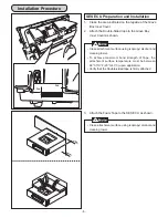
INSTALLATION MANUAL
Genuine Part # : H001SVA800
Vehicle Model : WRX/STI
Rev 1.0
Tools Required
Phillips Screwdriver
Flat Blade Screwdriver
10mm, 12mm Socket Wrench
Torque Wrench
Torque Screwdriver
10mm Offset wrench
Pliers
Volt Meter (Or Circuit Tester)
Side Cutters
Scissors
Utility Knife
Masking Tape
Electrical Tape
Trim Removal Tool
Isopropyl Alcohol
Cleaning Towel
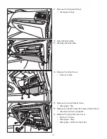
: Remove
: Tighten Torque
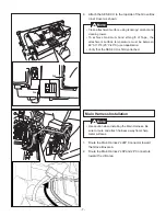
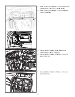
: Install
: Loosen
: Disconnect
: Discard
: Connect
: Location of Clip or Screw
: Re-use
Meaning of Characters
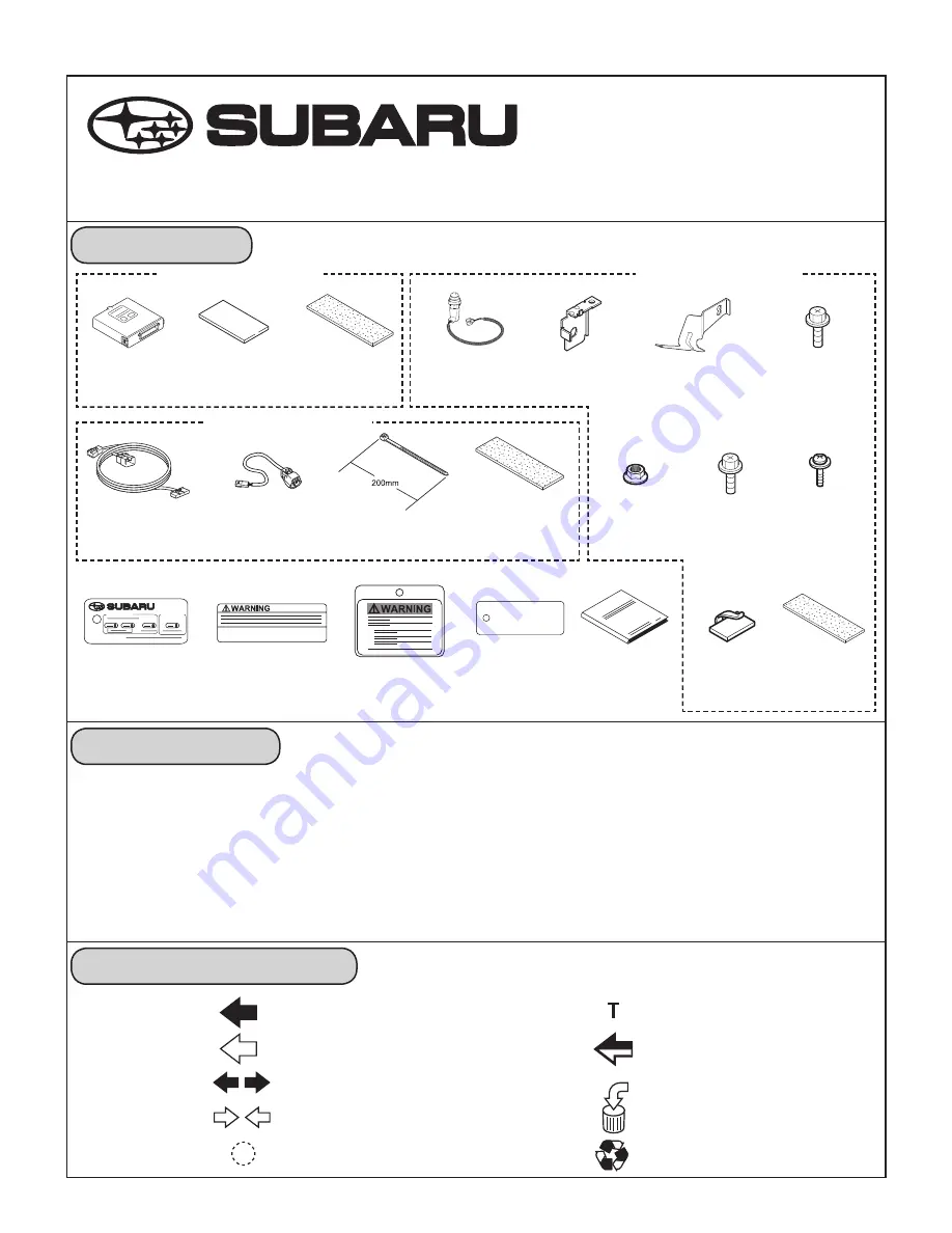
Kit Contents
NOTE: Laws in some communities require that the
vehicle be within view of anyone using the Smart
Engine Start. In some areas, use of the Smart
Engine Start may violate state, provincial or local
laws. Before using the Smart Engine Start, check
your state, provincial and local laws
Service P/N: H001SVA810
Service P/N: H001SVA820
Service P/N: H001SVA830
SES ECU
Quantity: 1
Double-sided tape
Quantity: 1
Foam tape
Quantity: 1
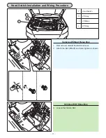
Hood Switch
Quantity: 1
Switch Holder
Quantity: 1
Hood Switch Bracket
Quantity: 1
Bolt (M6x16)(Black)
Quantity: 1
Main Harness
Quantity: 1
Sub-Harness
Quantity: 1
Tie Wrap
Quantity: 10
Foam tape
Quantity: 4
M6 Nut
Quantity: 1
Bolt (M8x20)
Quantity: 1
Screw
Quantity: 1
Key Tag
Quantity: 1
Engine Room Label
Quantity: 1
Wiper Lever Tag
Quantity: 1
Key Ring Tag
Quantity: 1
Owner's Guide
Quantity: 1
Harness Clamp
Quantity: 1
Foam tape
Quantity: 3


