SM-CB-ART2-L
Strong™ Carbon Series
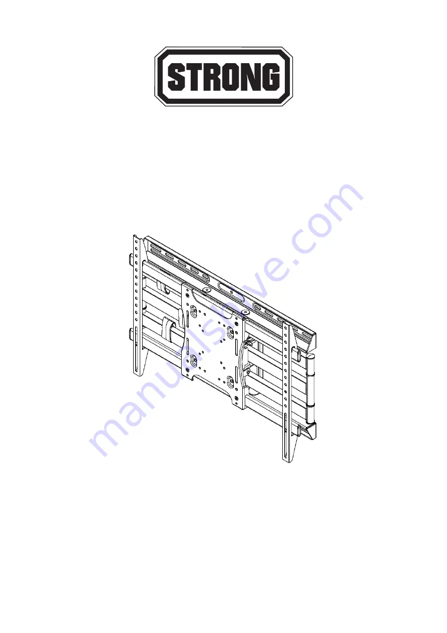
Universal Articulating Mount With Dual Arms
INSTALLATION MANUAL
Страница 1: ...SM CB ART2 L Strong Carbon Series Universal Articulating Mount With Dual Arms INSTALLATION MANUAL ...
Страница 2: ...tallation contactez un installateur professionnel pour obtenir de l aide Le mur ou la surface de montage doit être capable de supporter le poids combiné du support et de l écran sinon la structure doit être renforcée L installateur est responsable de la vérification du mur de la surface de montage et les ancrages utilisés peuvent supporter le poids total de l installation Un équipement de sécurité...
Страница 3: ...mm 5 Concrete Anchor C 10 50 mm 5 Screw D M6 20 mm 4 Screw E M6 40 mm 4 Screw F M8 20 mm 4 BAG 2 Screw G M8 40 mm 4 Screw H M8 50 mm 4 Spacer I 8 5 15 5 mm 4 Spacer J 8 5 17 5 19 mm 4 Spacer K 8 5 17 5 22 mm 4 BAG 3 M6 Washer L 6 4 18 2 mm 8 M8 Washer M 8 4 20 2 mm 8 Socket Wrench N 10 58 mm 1 ...
Страница 4: ...chor ATTENTION A standard electric drill on slow setting should be used to drill the holes instead of a hammer drill to avoid breaking out the back of the hole when entering a void or cavity 5 Drill holes Figure 1 NOTE Use 3 32 bit for drilling into wooden studs x4 NOTE Use 5 16 bit for drilling into concrete wall x6 NOTE Two additional holes and provided anchors are needed for concrete installs A...
Страница 5: ...horizontally centered on the back of the flat panel display NOTE There are eight positions for flexibility Move the Adapter Brackets to desired location Adapter Brackets can be flipped around if required 3 Attach the Adapter Brackets using four mounting bolts D H and four washers L or M NOTE Bolt size will depend on thread pattern and hole depth of the flat panel being installed 4 Once aligned tig...
Страница 6: ...d 4 Re install hex nuts and nylon washers securing mount head to arms ATTENTION This procedure requires two persons Ensure that the arm is set to its maximum negative tilt prior to attaching the display Figure 4 Cable Cover Attachment 1 Route electrical and data cables along the Arm Assembly and secure in place using the provided Cable Covers Figure 5 NOTE Ensure enough slack is provided to allow ...
Страница 7: ... tightening the unit by pulling the levers outward and then repositioning them to a vertical less obtrusive position Figure 6 Horizontal Adjustment 1 To adjust the horizontal angle of the display first slightly loosen the bottom two hex nuts with provided socket wrench N on back side of the Mount Head Then firmly hold opposite corners of the display and gently turn it into the desired position Whe...
Страница 8: ...y includes parts and labor repairs on all components found to be defective in material or workmanship under normal conditions of use This warranty shall not apply to products which have been abused modified or disassembled Products to be repaired under this warranty must be returned to Snap AV or a designated service center with prior notification and an assigned return authorization RA number ...