background image

Disposal Instructions 

49

10.

Power on the appliance using the power button.

11.

If the number of ports in the new module differs from the old 

module, modify the interface definitions as needed in the SSL VPN 

Web Console and save and activate the changes. See the 

SSL VPN 

Administrator’s Guide

 for details on modifying interface definitions.

Removing SFP Transceivers

If necessary, you can remove the SFP transceivers from the SFP ports.

To remove an SFP transceiver

1.

Connect to the engine command line as described in 

Connecting 

to Engine Command Line

 (page 41).

2.

Shut down the engine:

If the appliance is powered on, press Enter, log in as the user 

root

 with the password you set through the Web Console (see 

Enabling Command Line Access

 (page 41), and issue the 

command 

halt.

3.

Unplug all power cords from the system or the wall outlets.

4.

Disconnect the cable from the SFP transceiver.

5.

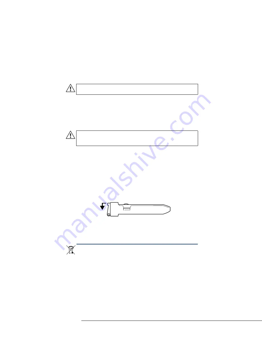
Pull down the latch on the SFP transceiver.

6.

Pull the SFP transceiver carefully out of the port slot.

If you want to replace the SFP transceiver you have removed, follow the 

instructions in 

Connecting Cables to SFP Ports

 (page 21).

D i s po s a l   I n s t r u c t i o n s

Dispose of the appliance separately from household waste at an 

appropriate waste disposal facility at the end of its useful service life.

Caution – 

Do not power on the appliance if you have not installed an 

interface module or a placeholder module in the appliance.

Caution – 

Invisible laser radiation is emitted from the end of fiber-

optic cable and from fiber port. Do not stare into the beam and avoid 

direct exposure to the beam.

Содержание SSL-3200 Series

Страница 1: ...Appliance Installation Guide SSL 3200 Series...

Страница 2: ...ce services for the products described in these materials are provided pursuant to the general terms for support and maintenance services and the related service description which can be found at the...

Страница 3: ...End User License Agreement which can be found at the Stonesoft website Contents Installation Procedure 4 Product Documentation 4 Safety Precautions 5 Unpacking the Appliance 8 Front Panel 8 Back Panel...

Страница 4: ...d Connecting the Cables page 19 4 Configure the basic system settings time interfaces and routing and import the license and a certificate See Configuring the Appliance page 23 Product Documentation T...

Страница 5: ...ll cause electrical shock Use extreme caution when using metal tools which can easily damage any electrical components or circuit boards they come into contact with Do not use mats designed to decreas...

Страница 6: ...sible The appliance inlet must have SPS approval or have at minimum a 15 AWG wire provided for the power supply The Mains Supply plug on the power supply cord is the disconnect device of the appliance...

Страница 7: ...the appliance Otherwise the appliance or the interface modules may be damaged Lithium Battery Precautions For California Perchlorate Material special handling may apply See www dtsc ca gov hazardouswa...

Страница 8: ...arrier who delivered the appliance or the components Front Panel On the front panel there are slots for the interface modules a Solid State Disk SSD Drive two USB ports and a serial port There are two...

Страница 9: ...When flashing indicates a fan failure When continuously on indicates overheating which may be caused by cables obstructing the airflow in the system or the ambient room temperature being too warm Ind...

Страница 10: ...w Back Panel Table 3 SSD Drive Indicators Indicator Status Explanation Power Blue A Solid State Disk is in the drive Disk Unlit This indicator is not currently used Disk Power AC or DC Power Connector...

Страница 11: ...t panel see the illustration in Front Panel page 8 3 Press the release button on the Solid State Disk to release the lever on the disk 4 Insert the disk into the drive 5 Press the lever down to lock t...

Страница 12: ...trap to your wrist so that it contacts your bare skin and attach the other end of the strap to the appliance 3 Select the slot where you want to install the interface module 4 Push the module into the...

Страница 13: ...noise and electromagnetic fields are generated Leave enough clearance in front of the rack to enable you to open the front door completely 63 cm 25 inches Leave enough clearance in the back of the rac...

Страница 14: ...onents are securely fastened to the appliance to prevent components falling off from the appliance Be sure to install an AC power disconnect for the entire rack assembly This power disconnect must be...

Страница 15: ...ckets 3 Align the holes against the two supports towards the rear of the appliance and push the bracket under the supports The brackets are marked with L for left and R for right 4 Secure the bracket...

Страница 16: ...nce into a four post rack 1 Locate the two pairs of brackets in the delivery package two inner rails that attach to the appliance and two outer rails that attach to the rack 2 Detach the inner rails f...

Страница 17: ...ponding buttons 5 Secure the rail to the appliance with a screw 6 Repeat steps 3 5 on the other side of the appliance 7 Insert the outer rails to the rack If necessary push the locking tab on the rail...

Страница 18: ...10 Slide the inner rails into the outer rails keeping the pressure even on both sides you may have to press the locking tabs when inserting When the appliance has been pushed completely into the rack...

Страница 19: ...rk can manage the appliance remotely if they learn the port s IP address and gain access to the credentials needed for remote management Caution Do not connect the appliance to an untrusted network th...

Страница 20: ...ure the appliance Configure the computer you use for connecting to the appliance to use an IP address in the same network 192 168 100 0 24 See Configuring the Appliance page 23 for information on how...

Страница 21: ...P transceiver Cable Types Make sure that the copper cables are correctly rated CAT 5e or CAT 6 in gigabit networks Speed Duplex Settings Network cards at both ends of each cable must have identical sp...

Страница 22: ...d connecting both power connectors to a power source to guarantee that the appliance can function even if one of the power connectors fails 2 Plug the power cords into grounded high quality power stri...

Страница 23: ...P address and other default settings for the appliance in the Engine Configuration Wizard To start the Engine Configuration Wizard 1 Connect the supplied null modem cable to the serial port on the app...

Страница 24: ...ocal Timezone and press Enter 2 Select the correct timezone in the dialog that opens Note If the desired keyboard layout is not available use the best matching available layout or select US_English No...

Страница 25: ...Netmask The default IP address of the SSL VPN Web Console is 192 168 100 1 4 Optional Enter the Web Console IP Default Gateway IP address through which outgoing traffic is routed 5 Optional Highlight...

Страница 26: ...s Web Console IP Address 10000 The SSL VPN Web Console login page opens If you did not change the SSL VPN Web Console IP address in the Engine Configuration Wizard the address is the default SSL VPN W...

Страница 27: ...eb Console and the SSL VPN Administrator 1 In the SSL VPN Web Console expand System in the menu on the left and select Admin Password 2 Enter a new password in both fields on the right and click Chang...

Страница 28: ...em Time section and click Apply 4 Synchronize the times by clicking Copy from system time Configuring Interfaces You must add at least one interface in addition to the management port to offer service...

Страница 29: ...ck Network Interfaces 3 Under Interfaces Activated at Boot Time click Add a new interface above or below the interface table 4 Enter the Name for the interface 5 Select how the IP address is assigned...

Страница 30: ...guring Routing To configure routing 1 In the SSL VPN Web Console under the Networking category in the menu on the left select Network Configuration 2 On the right click Routing and Gateways The Routin...

Страница 31: ...pplied or the appliance is rebooted For example you can create a temporary route for testing or for temporarily creating connectivity to a particular network To add temporary routes 1 Click Routing an...

Страница 32: ...a Certificate Request Authentication in SSL is based on certificates as the proof of identity The appliance contains a factory installed certificate that allows testing in a closed network without th...

Страница 33: ...nd line and run the makecsr script that was extracted from the archive 5 Fill in the required details Information on creating a certificate signing request can be found in the SSL VPN Administrator s...

Страница 34: ...t to the SSL VPN Administrator and activate it for the Administration Service and Access Point See Logging in to the SSL VPN Administrator and Importing Certificate Keys and Certificates page 37 Loggi...

Страница 35: ...Administrator Password section 4 Optional Deselect Enable Password Policy if you do not want to require the password to meet specific security requirements 5 Enter the Current Password 6 Enter and con...

Страница 36: ...as well See the Stonesoft Administrator s Guide or the Online Help of the Management Client for more information To import a license 1 After you log in and change your password select License in the...

Страница 37: ...To import a certificate key and certificate 1 In the SSL VPN Administrator switch to the Manage System section at the top menu 2 Select Certificates in the menu on the left The Manage Certificates pa...

Страница 38: ...Browse and select the private certificate key file private pk8 Password If you protected the certificate key with a password when you generated it type in the same password here 5 Click Save This impo...

Страница 39: ...iance 39 4 Select Access Points in the menu on the left 5 Click Access Point under the title Registered Access Points 6 Select the Server Certificate from the list 7 Scroll to the bottom of the page a...

Страница 40: ...trolled with Access rules based on user groups 3 Defining Access rules for allowing access to the services on the appliance 4 Defining the services you want to offer In addition to other services you...

Страница 41: ...e menu on the left and select Root Password 3 On the right type in and confirm the command line password for the account root The root account is always the only account for command line access 4 Opti...

Страница 42: ...nagement port eth0_0 on the appliance s back panel at the address https Web Console IP Address 10000 For detailed instructions for establishing the local connection see Logging in to the SSL VPN Web C...

Страница 43: ...w or through the SSL VPN Web Console as described in Enabling Command Line Access page 41 To change the root password in the Engine Configuration Wizard 1 Connect to the engine command line as describ...

Страница 44: ...front panel and to a computer 2 On the computer open a terminal with the following settings 9600 bps 8 databits 1 stopbit no parity 3 Re start the appliance If the appliance is powered on press Enter...

Страница 45: ...6 Select System Restore Options and press Enter 7 Type 1 and press Enter to clear the settings A confirmation prompt is shown 8 Type YES and press Enter to perform the reset If you decide to cancel t...

Страница 46: ...the AC power supply module 2 Locate the release tab on the left side of the power supply 3 Push the release tab to the right to release the power supply from its locking position 4 Pull out the power...

Страница 47: ...and issue the command halt 3 Unplug all power cords from the system or the wall outlets 4 Locate the Solid State Disk drive on the appliance s back panel see Back Panel page 10 5 Press the release bu...

Страница 48: ...powered on press Enter log in as the user root with the password you have set for the appliance and issue the command halt 3 Unplug all power cords from the system or the wall outlets 4 Disconnect al...

Страница 49: ...ugh the Web Console see Enabling Command Line Access page 41 and issue the command halt 3 Unplug all power cords from the system or the wall outlets 4 Disconnect the cable from the SFP transceiver 5 P...

Страница 50: ...documentation See inside for further details All documentation and our technical knowledge base is available at www stonesoft com support Copyright 2013 Stonesoft Corporation Stonesoft Inc Americas He...

Отзывы: