


SR/AI
SR/AP
Hardware Reference
Release r09
Page 23 of 76
3.12 Slow Clock Interface
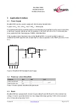
Consumption of power during power-down modes can be reduced by feeding the module with an
optional 32,768 kHz slow clock at pin SLCK.
SLCK specification:
32,768 kHz typ., 30 kHz min., 35 kHz max. Duty cycle 30...70%.
Signal must be square wave, at VSUP-level (see note below) and present as long as VSUP
is powered.
The module’s firmware will detect the presence of a slow clock during the boot process and switch
behavior appropriately. This check does only apply for presence of some clock; it is
not
checked if
the clock frequency is in the valid range required by CSR8811 (30kHz ... 35kHz).
If this signal is not used, to minimize risk of erroneous pulse detection in noisy environments,
Stollmann recommends the connection of A-6 to GND (direct connection or pull-down resistor).
Note: Since SLCK is fed to both the STM32 and the CSR8811, the electrical characteristics as
described in Table 11 (V
LSEH
) and Table 12 (V
IH
) apply at the same time.
3.13 Test Mode Enable
This functionality is reserved. Leave pin TESTMODE# open.
3.14 Pin Strapped System Memory Boot Mode Invocation
Asserting BOOT0 “high” will invoke the system memory bootloader at start-up. This is required for
firmware update. Thus, access to this signal and a means to drive it at high level should be
foreseen by the
customer’s hardware. While not in use, this signal can be left open or driven to
logic low level.
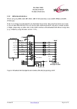
To connect to the module during system memory boot mode, an RS232 serial interface has to be
directly linked to the UART-TXD (F-4) and UART_RXD (D-2) pins.
The bootloader is stored in the internal boot ROM memory (system memory) of MCU. It is
programmed during production. Its main task is to upgrade the firmware to the internal Flash
memory. A communication protocol is defined with a specific command set and sequences.
The firmware upgrade will be done by either
-
a Stollmann provided firmware update tool. This is a Windows
™ program that contains the
firmware and uses a PC with a serial port for the update
-
implementing the system memory boot mode protocol on the host system.
If firmware update shall be performed from a host MCU, signals BOOT0 and EXT-RES# both must
be controlled by that host MCU (GPIO ports). Please note that EXT-RES# must not be driven
directly from a push-pull signal (see chapter 3.3).
Содержание BlueMod+SR/AI
Страница 1: ...BlueMod SR AI BlueMod SR AP Hardware Reference Release r09 ...
Страница 56: ...BlueMod SR AI BlueMod SR AP Hardware Reference Release r09 www stollmann de Page 56 of 76 8 2 1 FCC Grant ...
Страница 57: ...BlueMod SR AI BlueMod SR AP Hardware Reference Release r09 www stollmann de Page 57 of 76 ...
Страница 60: ...BlueMod SR AI BlueMod SR AP Hardware Reference Release r09 www stollmann de Page 60 of 76 8 3 1 IC Grant ...
Страница 65: ...BlueMod SR AI BlueMod SR AP Hardware Reference Release r09 www stollmann de Page 65 of 76 ...
Страница 66: ...BlueMod SR AI BlueMod SR AP Hardware Reference Release r09 www stollmann de Page 66 of 76 ...
Страница 67: ...BlueMod SR AI BlueMod SR AP Hardware Reference Release r09 www stollmann de Page 67 of 76 ...


