Stoelting VB25 Freezer Скачать руководство пользователя страница 9

English
Operating instructions

9

-

The electric capacity of the system must exactly match the supply’s voltage and frequency required by the device;

-

the current capacity of the system must be suitable for the device’s input;

-

the system must end with an accepted 4 pole electric socket and with electric and mechanical suitable characteristics.
The electric socket’s poles must be marked with appropriate letters (phases R- S- T + earth);  the earth’s pole must be
recognizable;

-

the electric socket must prevent,  through appropriate mechanical measures,  the plug’s wrong connection;

-

the electric socket must have,  above or annexed,  a breaker,  conformed to the in force safety laws,  with an associated
gearing placed near the device,  in a position easily reachable by the operator.  It must also be protected by fuses,
above or annexed,  with characteristics suited at the current absorbed by the device.

A WRONG CONNECTION ON THE EARTH TERMINAL MAY CAUSE SERIOUS DANGER.

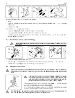
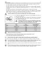
A 4 pole plug,  suitable with the current socket,  must be installed at the end of the
device's power supply cable.

The device’s power supply cable is composed by 4 coloured wires,  and eventually
marked with appropriate bands,  which must be connected to the relevant plug’s termi-
nals,  as shown in the following table.

A WRONG CONNECTION IN THE PLUG’S INSIDE MAY CAUSE SERI-
OUS DANGER. FOR THE CONNECTION, ONLY ADDRESS YOUR
SELVES TO QUALIFIED AND AUTHORIZED TECHNICIANS.

Kind

Wire

Wire

Code marked near

of supply

colour

marking band

plug’s terminal

EARTH

GREEN/YELLOW

None

PE or 

Phase R

BLACK

R or L1

Phase S

BROWN

S or L2

Phase T

BLACK

T or L3

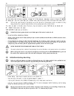
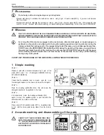
Before using the device it is necessary to:

-

connect it to the water network, if the device features a water condenser (Ref. Par. 5.4);

-

carry out the initial functioning checking (Ref. Par. 5.5).
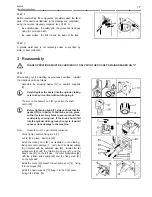
5.4

Connection to the water network (devices with water condensation)

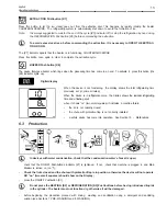
If your device features water condensation,  it is necessary to prepare tubes for the feeding and draining of the water.

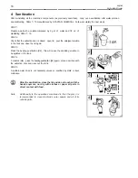
Do not let water from a TOWER in, unless they have been specifically designed to utilize water from a
tower. Unless otherwise specified, the machine is designed to utilize water from a WELL.

Note:

the correct water temperature to start the machine is specified in the Technical Handbook, Par. “Technical
data”.

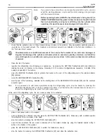
The use of below standard tubes and connections may cause water drops, with consequent inconven-
iences for Your laboratory and, if the drop is abundant with squirts, it damages the device.

Содержание VB25 Freezer

Страница 1: ...Model VB25 OPERATING MANUAL...

Страница 2: ...English Vertical batch freezer 2...

Страница 3: ...ORTANT SAFETY ADVICESAND PRECAUTIONS 4 2 SAFETY DEVICES 5 2 1 Lid s magnetic sensor 5 2 2 Extraction door s grill 5 3 TECHNICALDATA 5 3 1 Technical data plate and CE marking 5 3 2 Acoustic pressure le...

Страница 4: ...cess to the device s moving parts beater cylinder or extraction door Any modification of the electric supply must be exclusively performed by qualified and certified personnel Any use of the device th...

Страница 5: ...emicircle 5 on the bottom of the magnet 1 must coincide with the grooves 4 marked by a white line down the side and the stencilled semicircle 6 on top of the magnetic contact 2 The device will not wor...

Страница 6: ...hnicians carry out the transportation un packing and installation TO LIFT THE MACHINE ALWAYS USE AN ADEQUATE LIFTING DEVICE ATTEMPTING TO LIFT IT MANUALLY IT S DANGEROUS AND IT CAN DAMAGE YOUR HEALTH...

Страница 7: ...ropes or brackets for the lifting THROUGH the machine since those could damage the inside parts Re close the lateral panels Replace or move the packing which is produced with entirely recyclable mater...

Страница 8: ...sembled install it under the extraction door 14 by hooking it to the hinges 26 install the basin support 10 by fixing it to the front panel with knobs 16 5 3 Electric connection THE SUPPLY S VOLTAGE R...

Страница 9: ...s and eventually marked with appropriate bands which must be connected to the relevant plug s termi nals as shown in the following table A WRONG CONNECTION IN THE PLUG S INSIDE MAY CAUSE SERI OUS DANG...

Страница 10: ...in the device is higher it is necessary to interpose a pressure limiting device appropriately regulated above the delivery pipe AVOID CONSTRICTION OR NARROW TURNS OF THE TUBES Note The water outcomin...

Страница 11: ...T or S T Close the plug s shell plug in the device and repeat the checking 6 MACHINE S OPERATION 6 1 Warnings WHEN USING THE DEVICE AS WITH ALL ELECTRICAL APPARATUS ESSENTIAL RULES MUST BE COMPLIED WI...

Страница 12: ...ll automatically memorise as total time the minutes VISUALISED ON THE DISPLAY after having pressed one of the setting pushbuttons BEATING Pushbutton K2 By pressing the pushbutton the rotation of the b...

Страница 13: ...l refrigerating time previously set in prime minutes When the device is in refrigeration cycle the display shows the residual refrigerating time and a flashing spot when it shows oo two small squares...

Страница 14: ...and K4 and reading the value in minutes on the display Generally 8 to 12 minutes of refrigerationare necessary in function of the quality and quantity of the mixture press the BUZZER Pushbutton K6 to...

Страница 15: ...e REFRIGERATION Pushbutton K5 during the washing Otherwise you would freeze the water and break the parts of the machine Do not press the EXTRACTION Pushbutton K7 because all the washing solution woul...

Страница 16: ...ction door 40 taking extremely care not to damage its surface and not to loose its parts TAKE CARE NOT TO ALLOW WATER OR ANY LIQUID INSIDE THE MACHINE STEP 2 Prepare a pail with a solution composed by...

Страница 17: ...opping it The slot on the beater s hub 27 goes into the shaft clutch 28 Before tightening knob 7 always check that the gasket G is in perfect conditions and in place an that is clear of any fat as to...

Страница 18: ...in the tank and close the lid again STEP 3 Press the beating pushbutton K2 this will cause the sanitizing solution to be agitated in the tank STEP 4 5 minutes later press the beating pushbutton K2 aga...

Страница 19: ...ufacturer To correctly replace the gaskets it is necessary to remove the old gaskets by using a sharp tool possibly non metallic paying attention not to scratch the seating of the gaskets themselves c...

Страница 20: ...tion in rooms with a temperature lower than 0 C it is INDISPENSABLE to get rid of the water in the condensator and in the inlet and outlet pipes Call the Assistance Service 11 MALFUNCTIONS WE RECOMMEN...

Страница 21: ...w minutes and try again If the incon venient should not be eliminated or should frequently repeat call the assistance service Note it may be necessary to wait up to 30 minutes for the thermal protecti...

Страница 22: ...thermal protections to cool down Break down the refrigerating system or the electric controls Call the Assistance Service Unusual noises The noisiness comes mainly from the cylinder when the beating...

Страница 23: ...English Operating instructions 23...

Страница 24: ...Assistance Kundendienst Servicio Asistencia Servicedienst COSTRUTTORE MANUFACTURER CONSTRUCTEUR HERSTELLER CONSTRUCTO R FABRIKANT Via S Pertini 10 26845 CODOGNO LODI ITALIA Tel 0377 466650 Fax 0377 46...

Отзывы: