


STOBER
4 | Technical data
05/2019 | ID 442793.01
27
4.3
Safety technology
The SR6 option adds the STO safety function to the SC6 drive controller via terminal X12.
For double-axis controllers, the STO safety function has a two-channel structure that acts upon both axes.
Information
If you would like to use the STO safety function via terminals, be sure to read the SR6 manual; see the chapter
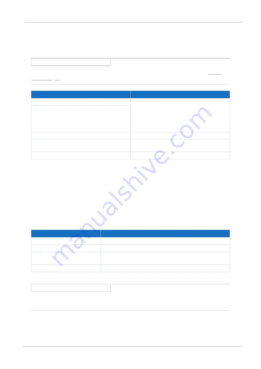
Specification
Electrical data
STO
a
U
1max
= 30 V
DC
(PELV)
high level = 15 – 30 V
DC
low level = 0 – 8 V
DC
I
1max
= 100 mA (typically < 30 mA for 24 V
DC
)
I
max
= 4 A
C
1max
= 10 nF
STO
b
STO
status
U
2
= U
1
− (1.5 Ω * I
1
)
STO
status
supply
U
1
= +24 V
DC
, +20%/25%
I
1max
= 100 mA
GND
—
Tab. 34: X12 electrical data
4.4
Controllable brakes
The brake of axis A is connected to X2A. Connect the brake of axis B to X2B for double-axis controllers.
You can control the following brakes:
§
Directly connected 24 V
DC
brakes
§
Indirectly connected brakes (e.g. over coupling contactor)
The brake is supplied over X300.
Electrical data
Brake output
U
2
24 V
DC
, +20 %
I
2max
2.5 A
f
2max
1 Hz at I
N
≤ 2.1 A;
0.25 Hz at I
N
> 2.1 A
E
2max
1.83 J
Tab. 35: Electrical data of the brake output
Information
In the case of a nominal brake current > 2.1 A, the system controller must ensure compliance with the maximum switching
frequency of 0.25 Hz.


