background image

Using the Touch Panel

HV1000 Video Switch

13618958, Rev A

Operation Manual for the International User Interface

12

To view the firmware version numbers: 

Tap the STERIS logo at the top of the touch screen.

The firmware version numbers for the touch screen and base unit are at the bottom of the screen, and the
STERIS logo appears in the center.

To return to the routing screen, tap anywhere on the screen.

Troubleshooting

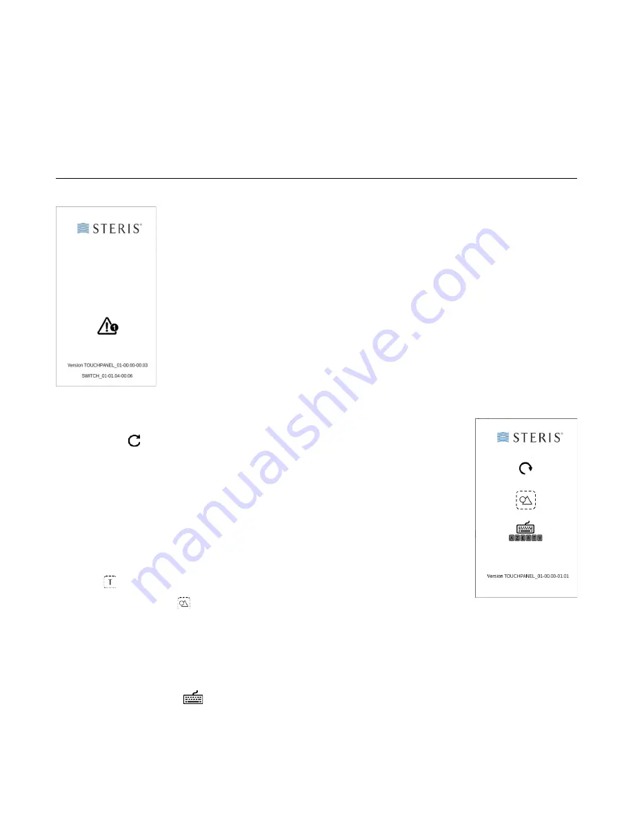
If a warning symbol appears: 

If the touch panel display is rotated the wrong way: 

If you see the wrong keyboard: 

1.

Tap the STERIS logo at the top of the touch panel:

2.

Tap the Keyboard icon 

 to switch between the QWERTY and AZERTY layouts

The AZERTY layout lets you enter accented characters, and the QWERTY layout does not.

3.

Tap the STERIS logo to return to the main screen.

If you see the screen at the left, the touch panel isn’t properly connected to the base unit.
Make sure the serial control connector between the base unit and touch panel is firmly
attached, and that both are receiving power. 

1.

Tap the STERIS logo at the top of the touch panel

2.

Tap Rotate 

.

The user interface changes from portrait to landscape mode, or from landscape to
portrait mode,

3.

Tap the STERIS logo to return to the main screen.

If the touch-panel displays English text where you expect to see icons: 

This affects the screens that let you add, delete, or edit a source or destination. To
change the labels used for sources and destinations on the main screen, see “To
customize the name of a source or destination” on page 11.

1.

Tap the STERIS logo at the top of the touch panel:

2.

Tap T 

It changes to Shapes 

. The icon based user interface is used instead of the text-

base interface.

Click the STERIS logo to return to the main screen.

Содержание HV1000

Страница 1: ...13618958 Rev A 2022 STERIS HV1000 Video Switch Operation Manual for the International User Interface XEH1BASE ...

Страница 2: ...ch This device complies with Part 15 of the FCC Rules Operation is subject to the following two conditions 1 this device may not cause harmful interference and 2 this device must accept any interference received including interference that may cause undesired operation Compliant with the UL AV 62368 standard Function Intended Application and Mode of Operation The HV1000 Video Switch is intended to...

Страница 3: ...angerous voltage This identifies equipment that emits non ionizing radiation This identifies a ground earth terminal Only suitable for use at areas with altitude less than 2000m Only suitable for use at non tropic climate areas This appears beside a product s unique device identifier This indicates that the product is a medical device When you dispose of this device or its parts make sure you prop...

Страница 4: ...d Location Use the device in a suitable environment See Operating Temperature and Storage Temperature in Specifications on page 14 Do not place the device near active high frequency medical electrical equipment such as magnetic resonance image MRI devices where the electromagnetic interference may be high Do not install near heat sources such as radiators heat registers stoves or other apparatus i...

Страница 5: ...adjustments or performance of procedures other than those specified herein may result in hazardous radiation exposure Waste Management Guidelines When you dispose of this device or its parts make sure you properly dispose of hazardous and other regulated waste in compliance with national state and local WEEE RoHS regulations ...

Страница 6: ...anging Settings 11 To add a source or destination 11 To delete a source or destination 11 To customize the name of a source or destination 11 To view the firmware version numbers 12 Troubleshooting 12 If a warning symbol appears 12 If the touch panel display is rotated the wrong way 12 If the touch panel displays English text where you expect to see icons 12 If you see the wrong keyboard 12 Mainte...

Страница 7: ...base unit fits on a desktop on a wall or in a standard sized rack The touch panel screen can be placed on a wall or desk The 4x3 model has four inputs two 4K HDMI and two HD fiber optic and three outputs all 4K fiber optic The 6x6 model has six inputs two 4K HDMI two HD fiber optic and two 4K fiber optic and six outputs all 4K fiber optic Here s a view of the base unit from the top Figure 1 1 HV10...

Страница 8: ...to look into them turn off the switch first Here s a close up view of the warning label Here are the ports on the base unit Figure 1 3 Warning label Figure 1 4 Close up of Ports 4x3 and 6x6 Power Input 4K Fiber Optic Outputs 4K HDMI Inputs HD Fiber Optic Inputs 4K Fiber Optic Inputs RS232 for Touch Panel Screen Power Output Power Input 4K Fiber Optic Outputs 4K HDMI Inputs HD Fiber Optic Inputs RS...

Страница 9: ... See To delete a source or destination on page 11 Edit See To customize the name of a source or destination on page 11 Sources and Destinations See To view the status of a source or destination on page 10 To view which destinations are displaying a source on page 10 and To route a source to a destination on page 10 Version See To view the firmware version numbers on page 12 Whenever you tap a butt...

Страница 10: ...o is routed to it If you have a STERIS A Series Surgical Lighting System HD with an In Light Camera that s connected to a fiber optic input that camera s source button does not show its status Tap the source All highlighted destination buttons are for destinations that are currently displaying the source All dimmed destination buttons are not To route a source to a destination 1 Tap the source All...

Страница 11: ...tch 4x3 model there is a maximum of 4 sources and 3 destinations 2 Tap the source or destination to add 3 Tap Confirm The new source or destination is now available for routing 1 Tap Delete 2 Tap the source or destination to delete 3 Tap Delete The deleted source or destination is longer be available for routing To re add the source or destination see To add a source or destination on page 11 1 Ta...

Страница 12: ... to return to the main screen If you see the screen at the left the touch panel isn t properly connected to the base unit Make sure the serial control connector between the base unit and touch panel is firmly attached and that both are receiving power 1 Tap the STERIS logo at the top of the touch panel 2 Tap Rotate The user interface changes from portrait to landscape mode or from landscape to por...

Страница 13: ...ything else harder than pencil lead Avoid touching it with anything greasy Do not set anything on top of it or attach anything to it Wipe any liquid off it immediately If the display is smudged wipe it with a soft dry cloth If the display is dirty moisten a soft dry cloth with either isopropyl alcohol or ethyl alcohol and gently wipe it Do not scrub hard The following substances are especially dam...

Страница 14: ...C 2A phoenix terminals 1 port used for Touch Panel Power Supply 100 240V AC 1 2 A 50 60Hz 140W Medical Grade Class 2 AC DC Power IEC 62638 and IEC 60950 I T E Safety IEC 60601 1 3rd Edition Medical Safety 60601 1 2 4th Edition EMC BF Leakage Current 2 MOPP Isolation Touch Panel Specifications Dimensions Width 4 75 in 12 07 cm Height 4 in 10 16 cm Orientation The touch panel can be installed in por...

Страница 15: ...onal User Interface 15 Operating Humidity 10 to 85 non condensing Storage Humidity 10 to 70 non condensing Altitude 6560ft 2000m Compliance This device meets the safety and emissions standard UL AV 62368 This device contains a class 3R laser product that complies with IEC 60825 1 Ed 3 ...

Страница 16: ...t Serious incidents that have occurred in relation to this medical device should be reported to the manufacturer and competent authority in the country where the incident occurred STERIS 5960 Heisley Road Mentor OH 44060 United States STERIS 503 Canal Blvd Richmond CA 94804 United States 1 800 548 4873 ORISupport STERIS com ...

Отзывы: