MODULES FOR STEPPER MOTORS
MODULES
TRINAMIC Motion Control GmbH & Co. KG
Hamburg, Germany
www.trinamic.com
V 1.04
HARDWARE MANUAL
+
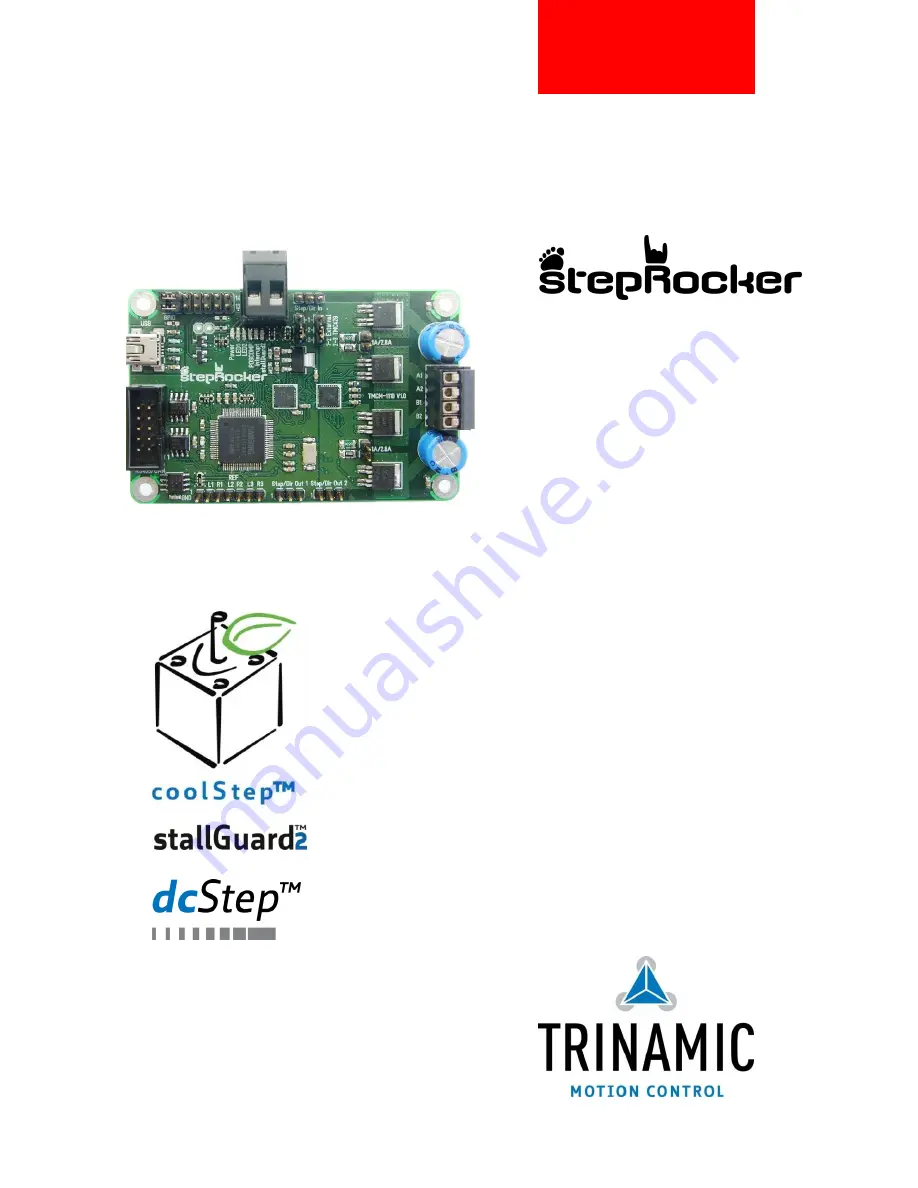
TMCM-1110 V1.1
1-axis stepper controller / driver
1A RMS / 2.8A RMS
24V DC
USB, RS485
U
NIQUE FEATURES
:
Страница 1: ...R STEPPER MOTORS MODULES TRINAMIC Motion Control GmbH Co KG Hamburg Germany www trinamic com V 1 04 HARDWARE MANUAL TMCM 1110 V1 1 1 axis stepper controller driver 1A RMS 2 8A RMS 24V DC USB RS485 UNIQUE FEATURES ...
Страница 2: ...r 8 4 2 4 Reference switch connector to TMC429 9 4 2 5 RS485 and CAN connector 9 4 2 6 USB connector 10 4 2 7 Step dir input connector motor 0 10 4 2 8 Step dir output connectors motor 1 and motor 2 10 4 2 9 µC programming interface 11 4 3 Jumper settings 12 4 4 LEDs 13 4 5 Communication 13 4 5 1 RS485 13 4 5 2 USB 14 4 5 3 CAN retro fit option 15 5 Functional description 16 5 1 Extensions of the ...
Страница 3: ...re equipment intended to support or sustain life and whose failure to perform when properly used in accordance with instructions provided can be reasonably expected to result in personal injury or death TRINAMIC Motion Control GmbH Co KG 2011 Information given in this data sheet is believed to be accurate and reliable However neither responsibility is assumed for the consequences of its use nor fo...
Страница 4: ...g additional boards as slaves Electrical data Supply voltage 24V DC 10 30V DC Motor current up to 1A RMS or 2 8A RMS can be selected with jumpers Mechanical data Board size 85mm x 55mm height 15mm max without mating connectors 4 mounting holes for M3 screws Interfaces RS485 host interface USB 2 0 host interface mini USB connector Step Dir input TTL level Step Dir outputs TTL level for multi axis a...
Страница 5: ...TRINAMICs TMCL Firmware with all available features For developing one s own firmware please refer to www steprocker com or www motioncontrol community org Order code Description Size of unit mm3 TMCM 1110 stepRocker The stepRocker is a 1 axes bipolar stepper motor controller driver module with RS485 and USB 85 x 55 x 15 Table 3 1 TMCM 1110 order codes Order code Description CABLE USB MINI USB min...
Страница 6: ...rd with the controller driver electronics has an overall size of 85mm x 55mm x 15mm without mating connectors It offers four mounting holes for M3 screws 3 2mm diameter All four mounting holes are connected to the ground plane signal and supply ground of the module 85 55 4 4 4 Ø 3 2 4 x M3 screws Figure 4 1 Board dimensions and position of mounting holes all values in mm ...
Страница 7: ...20 02 2 pol 5 08mm pitch shrouded header RIA 249 02 screw type terminal block pluggable centerline 5 08mm pitch Motor RIA 183 04 4 pol 3 5mm pitch shrouded header RIA 169 04 screw type terminal block pluggable centerline 3 5mm pitch USB USB mini female connector USB mini male connector RS485 CAN Low profile box header without locking bar type 8380 10 pol DIN 41651 2 54mm pitch Low profile IDC sock...
Страница 8: ...ut can be used as home switch input voltage range 0 10V resolution 12bit 0 4095 10 PHASE_A in General purpose I O or encoder input channel A 5V compatible internal pull up to 5V 11 OpenDrain_1 out Open drain output max 100mA 12 PHASE_B in General purpose I O or encoder input channel B 5V compatible internal pull up to 5V 13 OpenDrain_2 out Open drain output max 100mA 14 PHASE_Z in General purpose ...
Страница 9: ...el Direction Description 1 2 3 CAN_L bi directional Differential CAN bus signal inverting retro fit option 4 CAN_H bi directional Differential CAN bus signal non inverting retro fit option 5 GND Power GND Signal and system ground 6 RS485 bi directional Differential RS485 bus signal non inverting 7 RS485 bi directional Differential RS485 bus signal inverting 8 9 10 Table 4 7 RS485 CAN connector 4 2...
Страница 10: ...a step dir input connector for motor 0 Via this connector an external motion controller can be used together with the on board driver electronics For selecting an external motion controller instead of the on board TMC429 motion controller two jumpers have to be set please refer to chapter 4 3 Pin Label Direction Description 1 GND Power GND Signal and System ground 2 Step In in Driver step input si...
Страница 11: ...in 14 of the processor MODE0 VPP is used for mode setting ether to debug mode or to flash serial writing mode Mode 1 Mode 0 Mode setting 0 0 User normal debug mode Used pins SWDIO and SWDCLK 0 1 User flash serial writing mode Used pins F_SDAT and PHASEA The user program mode for flash memory programming and sector erasing uses the internal high voltage generator which is necessary for flash memory...
Страница 12: ...rrent Select motion controller Figure 4 3 Jumper of TMCM 1110 stepRocker TMCM 1110 STEPROCKER JUMPERS Jumper Label Description Select motor current 1A 2 8A Jumper plugged motor current up to 2 8A RMS Jumper unplugged motor current up to 1A RMS Select motion controller 1 2 External 2 3 TMC429 Set jumpers to select motion controller TMC429 on the module or external which have to be connected to Step...
Страница 13: ...OSCMP is available for triggering when moving over a programmable position Interrupt detected Interrupt This orange LED lights up upon interrupts The LED is connected to the nIND_SDO_C pin of the TMC429 stallGuard2 detected stallGuard2 This red LED light up upon stalling conditions The LED is connected to the SG_TST pin of the TMC262 Table 4 5 LEDs Figure 4 4 LEDs of the stepRocker 4 5 Communicati...
Страница 14: ...ignals on the bus it is recommended to use a resistor network connecting both bus lines as well defined logic levels In contrast to the termination resistors this network is normally required just once per bus Certain RS485 interface converters available for PCs already include these additional resistors e g USB 2 485 node n 1 node n Slave Slave termination resistor 120 Ohm 5V GND pull up 1k pull ...
Страница 15: ... taken into account when setting up a CAN network 1 BUS STRUCTURE The network topology should follow a bus structure as closely as possible That is the connection between each node and the bus itself should be as short as possible Basically it should be short compared to the length of the bus c node 1 node n 1 node n Host Slave Slave Slave CAN termination resistor 120 Ohm termination resistor 120 ...
Страница 16: ...commands for the stepRocker refer to www steprocker com The TMCL boot loader on the board can be used for downloading new TMCL programs including such personal extensions too The TMCM 1110 module contains the following main components ARM Cortex MO processor Core S3FN41F microcontroller with built in up to 256 Kbytes program flash memory and up to 32 Kbytes SRAM Processor is equipped with crystal ...
Страница 17: ...provides the possibility for extension to full 3 axis systems The stepRocker itself can be used as master or slave An example for extensions is shown below USB Master Motor 0 Motor 1 Motor 2 S D OUT S D IN S D IN 3 x REF IN GPI O USB RS485 only initialization and parameterization TMCL only initialization and parameterization USB RS485 Figure 5 2 TMCM 1110 stepRocker extension ...
Страница 18: ...SB Power supply via USB connector 5 V IUSB Current withdrawn from USB supply when USB bus powered no other supply connected 85 mA ICOIL Motor coil current for sine wave peak chopper regulated adjustable via software 0 1500 or 4000 mA IMC Continuous motor current RMS 0 1000 or 2800 mA TENV Environment temperature at rated current no forced cooling required 25 tbd 80 C Table 6 1 General operational ...
Страница 19: ...11 OCT 27 SD Minor changes 1 04 2011 OCT 31 SD Minor changes Figure 7 1 Document revision 7 2 Hardware revision Version Date Description TMCM 1110 V1 1 2011 SEP 02 Minor changes from version 1 0 to version 1 1 Figure 7 2 Hardware revision 8 References USB 2 485 USB 2 485 interface converter manual available on http www trinamic com TMC262 TMC262 datasheet manual available on http www trinamic com ...