

1.0 GENERAL
The SEM110 series are high performance two wire 4-20mA transmitters designed to
accept most standard industrial temperature, thermocouple, slide wire and variable
resistance sensors which operate over most common ranges. Automatic thermocouple
cold junction compensation is provided on thermocouple versions where the output
is directly referenced to the mV input, allowing linearisation to be carried out by the
loop monitoring instrumentation, if required. The device is potted inside a plastic
enclosure, suitable for head mounting into any DIN style enclosure. Screw terminals
are provided for wire connections. Trim potentiometers are provided to allow
calibration adjustments.
2.0 SEM110 SPECIFICATION @ 20 ºC
PART NUMBER
INPUT TYPE
SEM110TC
Isolated (Un-grounded)
Thermocouple
types K,T,J,R,S,N
SEM110P
PT100, PT10, PT1000
SEM110CU
Copper resistor
SEM110W
Slide Wire SEM110Z Variable resistance
SEM110D
Differential PT100
OUTPUT
4-20 mA two wire (Max 30 mA)
SUPPLY VOLTAGE
10 to 45 V DC reverse connection protected.
30 VDC Max I.S. version
AMBIENT TEMP
0 to 70 ºC operation, -40 to 100 ºC storage
AMBIENT HUMIDITY
0 to 95 % (non condensing)
CONNECTION
Screw Terminal, Recommended cable size
2.5mm sq.
ZERO DRIFT
±2µA/ºC
SPAN DRIFT
±100ppm/ºC
MAX LOOP RESISTANCE
700R (24V)
EMC
Conforms to BS EN 61326
3.0 INSTALLATION
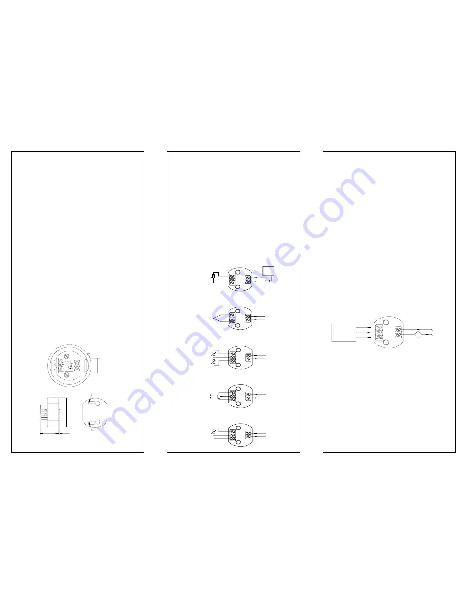
3.1 Mechanical
The transmitter is mounted using two 4.5mm diameter holes, on standard 33mm
fixing centres. This transmitter has been specifically designed to be mounted inside
a DIN standard probe head, which must provide adequate protection to moisture,
corrosive atmospheres etc. All cable entries should be sealed using the correct size
cable gland.
Care must be taken when locating the transmitter to ensure the ambient temperature
remains inside the specified range of 0 to 70 ºC. The diagram shows the mechanical
layout with a typical application of the transmitter mounted inside a probe head
enclosure.
3.2 Electrical
Connections to the transmitter are made to the screw terminals provided on the top face.
The SEM110 conforms to BS EN 61326 and as such, the radiated electromagnetic
susceptibility is tested to 3v/m. It is therefore recommend that during the installation
process, the instrument should be mounted away from any high powered radio
transmitters and away from any heavy switching gear.
To maintain EMC compliance input/sensor wires must be less than 3 metres long and
output wiring must use screened twisted pair cable with the screen earthed at one
end only.
All three input wires must have the same core diameter to maintain equal lead
resistance in each wire. T/C sensors must be ungrounded.
The transmitter is protected against reverse connection by means of a series diode,
therefore incorrect connection of the output wires will result in near zero
current flow in the loop. Incorrect connection or failure of the sensor wires will result
in the transmitter saturating, T/C versions go upscale, whilst resistance
sensor inputs go either upscale or downscale dependant upon which wire breaks.
The most common failure would be a total sensor burnout, in which case the
transmitter will go upscale.
3.3 CONNECTIONS
The diagram shows the method of connection to provide a 4-20 mA current loop output.
The Pt100 sensor shown as an example would normally take the form of a probe
assembly with a three wire output. Refer to connection drawing for other connection
types. The output loop shows a 24V DC power supply used to provide loop excitation,
the transmitter and a load all connected in series. The load symbol represents other
equipment in the loop e.g. indicators, controllers, loggers etc. Sometimes these
instruments come with the 24V supply built in as standard, this simplifies wiring and
reduces cost. Care must be taken when designing the 4-20mA circuit to ensure that
the total burden of the loop, that is the total voltage requirements of all the
equipment in the loop added together, does not exceed the power supply voltage. If
a number of instruments are connected in the loop, ensure that only one instrument
is tied to ground. Grounding the loop at two points will result in shorting out part of
the loop and therefore any instruments in that part of the loop will not operate.
4.0 CALIBRATION
Calibration is only recommended when the user has access to suitable equipment,
together with a reasonable knowledge of instrumentation calibration techniques. The
following instructions act as a guideline to calibration.
4.1 A precision calibrator will be required, to simulate the type of sensor the
transmitter is designed for, together with a set of tables giving the sensor
output against process variable, (e.g. resistance against temperature for a
PT100 sensor). A precision digital current meter together with a 24V DC
supply will also be needed. Read the SEM110 label to establish the
transmitter range i.e. the process variable input for 4mA and 20 mA. The
side label also indicates the location of the span and zero pots.
4.2 Connect calibrator to input terminals, using the correct compensation wire
for thermocouples inputs and three wire connection for RTD inputs.
Connect the output positive to +24V, negative to 0V via current meter. Turn
power on.
4.3 Set simulator to 4mA process variable and adjust ZERO trimmer for
4.000 mA output. ±0.002mA
4.4 Set simulator to 20mA process variable and adjust SPAN trimmer for
20.000 mA output ±0.002 mA.
4.5 Repeat steps 4.3 and 4.4 until both points are in calibration.
4.6 Turn power off and remove calibration equipment.
5.0 SEM110X\* VERSIONS - FOR USE IN POTENTIALLY EXPLOSIVE
ATMOSPHERES
5.1 ATEX Certificate
The SEM110X\* models has been issued with a EC-type examination certificate,
confirming compliance with the European ATEX directive 94/9/EC for :-
Intrinsic safety
II 1 G EEx ia IIC T5.
The equipment bears the Community Mark and subject to local codes of practice,
may be installed in any of the European Economic Area (EEA) member countries.
The SEM110X housing is coloured light blue to identify the equipment as suitable for
Hazardous area use. The equipment must be installed and maintained in accordance
with local requirements for electrical equipment for use in potentially explosive
atmospheres, eg EN60079-14 & EN60079-17. This instruction sheet describes
installation which conforms with BS EN60079-14 & BS EN60079-17 Electrical
Installation in Hazardous Areas. When designing systems outside the UK, the local
Code of Practice should be consulted.
32.0
1.8
53.0
Zero
Span
Mounting holes: 2 holes 4.5mm diameter, 33mm centres
LOAD
POWER
(24V N OM )
SU PPLY
-
+
Ra-Rb
Rb
Ra
20mA
4mA
Pt100, 3wire
TC, Isolated, junction only
Type D, Differential Temperature
Type W, Slide Wire
Type Z, Variable Resistor
-
SEM110X
CALIBRATOR
DC
+
-
+ 24V
A


