Installation
32
Instruction Manual SCE
3
is
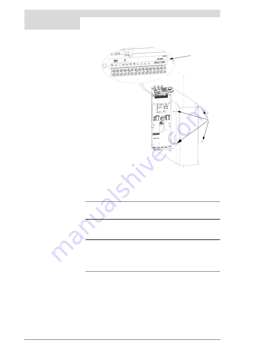
By way of preparation, first disassemble the protective cap from the control
column:
1. Undo the 4 screws
a
and remove the protective cap
2
from the electrical
section. The connecting block
3
is now visible.
n
Remark
Consult
before connecting any electrical
components.
3.10.3
Mains voltage
The appliance is supplied without a supply cable and main switch.
n
Remark
To supply the appliance with voltage, the appliance has to be connected to
the mains voltage by means of a permanent electrical connection. A two-
terminal main switch with a contact gap of at least 3 mm must be fitted
between this fixed connection and the appliance. The supply cable must
incorporate cores measuring a minimum of 3 x 1.0 mm
2
.
1. Feed the supply cable through the metric pull relief on the top of the control
column.
2. Connect earth (
A
), phase (L
1
) and neutral (N) on the supply cable to points
1 to 3 in the connecting block as set out in
3. Tighten the pull relief so that the cable is jammed.
4. If you do not need to make any more connections, then fit the protective cap
on the control column.
Figure 3.6
Connecting block (connections 1 to 15 explained in
IMD-0134
1
15
b
c
a
Содержание SCE 65-400
Страница 2: ...your installer ...
Страница 4: ...4 SCE Instruction Manual ...
Страница 8: ...8 Instruction Manual SCE gis ...
Страница 12: ...Introduction 12 Instruction Manual SCE 1 gis ...
Страница 18: ...Operating the appliance 18 Instruction Manual SCE 2 gis ...
Страница 20: ...Installation 20 Instruction Manual SCE 3 is Figure 3 1 Top and front of the appliance IMD 0145 ...
Страница 42: ...Installation 42 Instruction Manual SCE 3 is ...
Страница 46: ...Filling and draining 46 Instruction Manual SCE 4 gis ...
Страница 64: ...Maintenance 64 Instruction Manual SCE 9 s ...
Страница 67: ...Release R 1 0 Uk 67 A Appendices A 1 Introduction This appendix contains The Electrical diagram SCE is ...
Страница 70: ...Appendices 70 Instruction Manual SCE A is ...


