Quick-Start Guide
To view manuals, FAQs, videos, drivers, downloads, technical drawings, and more, visit www.startech.com/support.
Manual Revision: March 24, 2020 4:11 PM
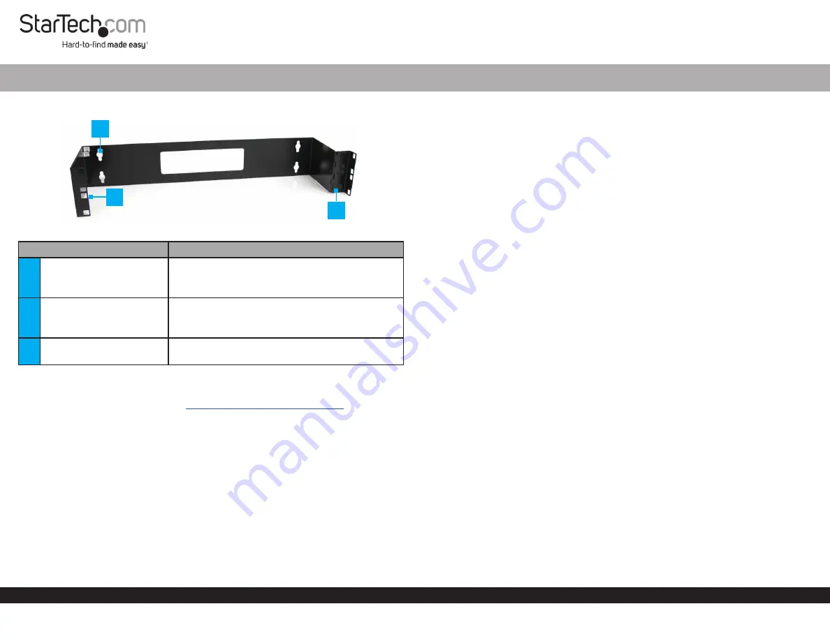
Product Diagram (WALLMOUNTH2)
Component
Function
1
Mounting Holes (4)
•
Used to mount the
Wall Mount Bracket
to a
Wall
.
•
Maximum weight capacity = 10 kg (22 lb).
2
Equipment Mounting
Holes
•
Used to mount a
Patch Panel
in the
Wall Mount
Bracket
.
•
Maximum height = 2U.
3
Hinged Side Panel
•
Used to access the back of the installed
Patch
Panel
.
Requirements
For the latest requirements, please visit
www.startech.com/WALLMOUNTH2
•
Phillips Head Screwdriver x 1
•
(Optional) Cage Nut Tool x 1
Installing the Wall Mount Bracket
Warnings:
If you lack the necessary expertise to attach this product to the wall, consult a
professional to install the Wall Mount Bracket or to provide specific mounting instructions
for your wall structure.
Make sure that the type of wall structure and mounting hardware that you are using will
properly support the mounted equipment. Failure to do so might result in personal injury
and/or equipment damage. The wall structure should be capable of supporting at least
four times the weight of the mounted equipment.
2U 19in Steel Hinged Wall Mount Bracket for Patch Panels
Installing a Patch Panel into the Wall Mount Bracket
Note:
Do not add equipment to the
Wall Mount Bracket
until it is securely attached
to the wall.
1.
Insert the one end of the
M6 Cage Nut
(included) into the
Equipment Mounting
Hole
. Push the other end of the
M6 Cage Nut
into the
Equipment Mounting Hole
,
until you hear it snap (lock) into place.
Note:
It is recommend that you use a
Cage Nut Tool
(sold separately) to aid with the
installation of the
Cage Nuts
.
2.
Repeat step 1 to install the remain
M6 Cage Nut
(2 per side) into the
Wall Mount
Bracket
.
3.
Line up the
Mounting Holes
on the
Patch Panel
with the
M6 Cage Nuts
on the
side
of the
Wall Mount Bracket
with the
Hinged Side Panel
.
4.
Insert 2
M6 Screws
(included) through the
Mounting Holes
on the
Patch Panel
and
into the
M6 Cage Nuts
.
5.
Connect any required
Cables
to the back of the
Patch Panel
.
6.
Line up the
Mounting Holes
on the other side of the
Patch Panel
with the
M6 Cage
Nuts.
7.
Insert 2
M6 Screws
through the
Mounting Holes
on the
Patch Panel
and into the
M6 Cage Nuts
.
8.
Using a
Phillips Head Screwdriver
(sold separately) tighten the
M6 Screws
.
Accessing the Back of a Patch Panel
1.
While supporting the weight of the
Patch Panel
, use a
Phillips Head Screwdriver
to unscrew two
M6 Screws
from the
Cage Nuts
, leaving the other two
M6 Screws
attached to the side of the
Wall Mount Bracket
with the
Hinged Side Panel
.
Note:
Make sure that there is enough clearance for the
Patch Panel
to free swing
away from the
Wall Mount Bracket
, before accessing the back of the
Patch Panel
.
2.
Gently swing the
Patch Panel
away from the
Wall Mount Bracket
to gain access to
the back of the
Patch Panel
.
3.
Reattach the two
M6 Screws
removed in step 1.
1
2
3


