

Instruction Manual
DE:
Bedienungsanleitung - de.startech.com
FR:
Guide de l'utilisateur - fr.startech.com
ES:
Guía del usuario - es.startech.com
IT:
Guida per l'uso - it.startech.com
NL:
Gebruiksaanwijzing - nl.startech.com
PT:
Guia do usuário - pt.startech.com
Manual Revision: 09/01/2011
For the most up-to-date information, please visit: www.startech.com
Packaging Contents
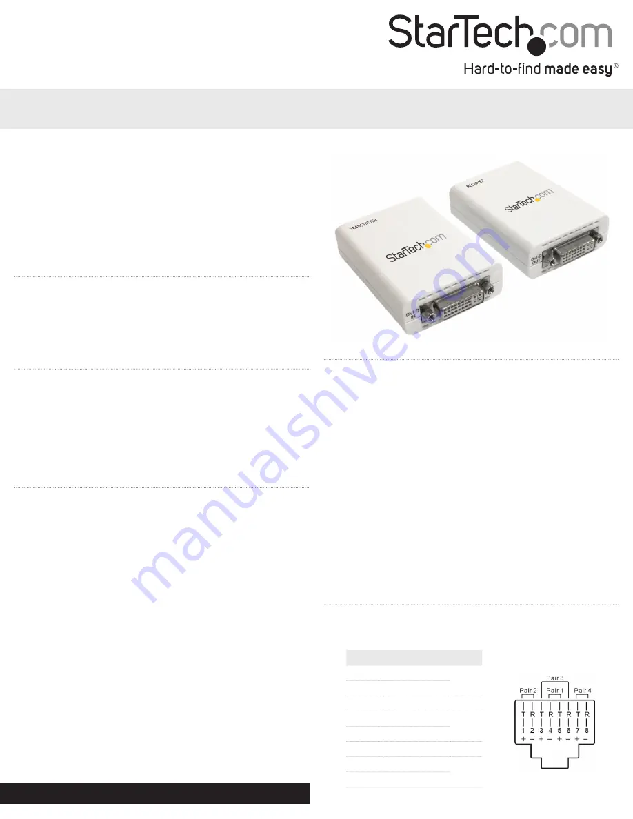
• 1 x Video Extender Transmitter
• 1 x Video Extender Receiver
• 2 x Universal Power Adapter
• 1 x Instruction Manual
System Requirements
• DVI-D/HDMI enabled video source device (e.g. computer)
• DVI-D/HDMI enabled display device (e.g. monitor, projector)
• Available AC electrical outlet for transmitter and receiver
• DVI-D/HDMI cable from receiver to display
• DVI-D/HDMI cable from video source to transmitter
• Cat6 UTP Ethernet cable (see “Preparing Your Site”)
ST121DVI25
ST121HD25
DVI Video Extender over Cat 6 UTP
High Speed HDMI® over Cat 6 UTP
Installation
1. Turn off the video source (i.e. computer) and the intended display
device (i.e. monitor).
2. Position the Receiver Unit near the remote display.
3. Position the Transmitter Unit near the video source.
4. Connect the video source to the DVI/HDMI port on the rear panel
of the Transmitter Unit, using a male/male cable.
5. Connect the remote display to the DVI/HDMI port located on the
rear panel of the Receiver Unit using a male/male cable.
6. Connect the Transmitter Unit to the Receiver Unit, using standard
RJ45 terminated UTP Cat6 cable (see “Preparing Your Site”).
7. Connect the power adapters (provided) to both Transmitter and
Receiver Units.
NOTE:
Both units can also be powered from a local USB port, by
using a USB cable (sold separately). You may also only connect
power to the Transmitter Unit, however maximum UTP cable length
will be reduced to 20m.
8. Turn on the display device first, followed by the video source.
Preparing Your Site
1. Determine where the local video source (i.e. computer) will be
located and set up the device.
2. Determine where the remote display will be located and place/
mount the display appropriately.
Please note
that both extender units will require a power
connection, so please ensure that each unit will be situated near an
available AC electrical outlet.
3. If you are using surface cabling, ensure you have enough Cat6
unshielded twisted pair (UTP) Ethernet cabling to connect the
Local Unit to the Remote Unit’s location, and that each end is
terminated with a RJ45 Ethernet connector. The cabling should
not go through any networking equipment (i.e. router, switch).
OR
If you are using premise cabling, ensure that the Cat6 unshielded
twisted pair (UTP) Ethernet Cabling between the Local Unit and
the Remote Unit has been properly terminated in a wall outlet/
panel in each location and there is a patch cable long enough to
connect the Remote Unit and the Local Unit to their respective
outlets. The cabling should not go through any networking
equipment (i.e. router, switch).
Wiring Diagram
The UTP cable must be wired according to the EIA/TIA 568B industry
standard as shown below.
Pin
Wire Color
Pair
1
White/Orange
2
2
Orange
3
White/Green
3
4
Blue
1
5
White/Blue
6
Green
3
7
White/Brown
4
8
Brown
*actual product may vary from photos
ST121DVI25


