


6. SPI Operations
This chapter describes how to configure and debug SPI GPIO.
6.1. Configuring SPI GPIO
The DTSI file,
jh7110-visionfive-v2.dtsi
, is under
/linux/arch/riscv/boot/dts/starfive
.
7 channels of SPI bus are supported: spi0 to spi6.
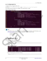
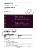
6.1.1. Modify Pins
The configured SPI GPIO number is the number indicated in the Pin Name. For more details about the GPIO Pin Name, see the
in this document. You can configure the unoccupied pins. The following are the default settings in the
jh7110-visionfive-v2.dtsi
:
Figure 6-1 Modify Pins
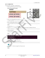
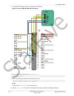
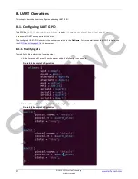
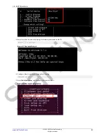
6.2. Debugging SPI GPIO
This section provides steps for loopback test and testing SPI with the ADXL345 module.
© 2018-2022 StarFive Technology
All rights reserved
20
StarFive


