background image

| 5 - I2C Operations

5.1.2. Configuring dts File

7 channels of I2C bus are supported: i2c0 to i2c6.
The DTSI file, 

jh7110-visionfive-v2.dtsi

, is under 

/linux/arch/riscv/boot/dts/starfive

.

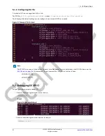
The following is the default setting. You can configure the unoccupied GPIOs as required.

Figure  5-2 Example File Content

Note:

The I2C GPIO pin number is the number indicated in the 

Pin Name

. For more details about the GPIO Pin Name, see the 

GPIO Pinout 

 (on page 9) 

 in this document. The pin names of the I2C GPIO are listed as follows:

GPIO58 (I2C SDA)

GPIO57 (I2C SCL)

5.2. Debugging I2C GPIO

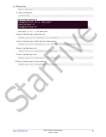
Perform the following steps to debug I2C:

1. Execute the following command to scan the bus:

i2cdetect -l

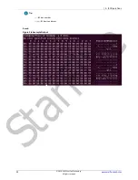
Result:

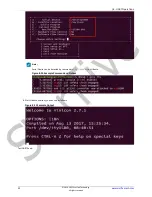
Figure  5-3 Example Output

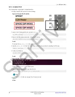
2. Execute the following command to detect the device:

i2cdetect -y -r 0

17

© 2018-2022 StarFive Technology 

All rights reserved

www.starfivetech.com

StarFive

Содержание VisionFive 2

Страница 1: ...VisionFive 2 40 Pin GPIO Header User Guide Version 1 1 Date 2022 12 27 Doc ID VisionFive2 UGEN 001 S t a r F i v e ...

Страница 2: ...ll liability including without limitation indirect incidental special exemplary or consequential damages All material appearing in this document is protected by copyright and is the property of StarFive You may use this document or any part of the document for internal or educational purposes only provided you do not modify edit or take out of context the information in this document in any manner...

Страница 3: ... official release 1 1 2022 12 27 Updated GitHub Repository on page 11 Notes and notices The following notes and notices might appear in this guide Tip Suggests how to apply the information in a topic or step Note Explains a special case or expands on an important point Important Points out critical information concerning a topic or step CAUTION Indicates that an action or step can cause loss of da...

Страница 4: ... SPI Operations 20 6 1 Configuring SPI GPIO 20 6 1 1 Modify Pins 20 6 2 Debugging SPI GPIO 20 6 2 1 Loopback Test 21 6 2 2 Testing SPI with ADXL345 Module 22 7 PWM Operations 25 7 1 Configuring PWM GPIO 25 7 1 1 Modify Pin 25 7 1 2 PWM and Pin Name Mapping 25 7 2 Debugging PWM GPIO 25 8 UART Operations 27 8 1 Configuring UART GPIO 27 8 1 1 Modifying dts 27 8 2 Debugging UART GPIO 28 8 2 1 Hardware...

Страница 5: ...Contents 9 2 1 Hardware Setup 35 9 2 2 Executing Example 37 5 2018 2022 StarFive Technology All rights reserved www starfivetech com S t a r F i v e ...

Страница 6: ...sitory Addresses 11 Table 5 1 Connect Sense Hat B to the 40 Pin Header 16 Table 7 1 PWM and Pin Name Mapping 25 Table 8 1 UART and DEV Mapping 28 Table 9 1 Connect Sense Hat B to the 40 Pin Header 33 Table 9 2 Connect 2 4inch LCD with 40 pin Header 35 www starfivetech com 2018 2022 StarFive Technology All rights reserved 6 S t a r F i v e ...

Страница 7: ...igure 7 1 Example File Content 25 Figure 8 1 Example Configuration 27 Figure 8 2 Example Configuration 27 Figure 8 3 Example Configuration 28 Figure 8 4 Connect the Converter to the Header 29 Figure 8 5 Example Configuration 29 Figure 8 7 Example Output 30 Figure 8 8 Example Configuration 30 Figure 8 10 Example Command and Output 31 Figure 8 11 Example Output 31 Figure 8 12 Test UART Send 32 Figur...

Страница 8: ...der as described in the Peripheral Examples on page 33 chapter 1 1 40 Pin Header Definition The following figure shows the location of the 40 pin header on VisionFive 2 Figure 1 1 40 Pin Definition 1 3 5 7 9 11 17 19 23 27 31 35 13 15 21 25 29 33 37 39 2 4 6 8 10 12 18 20 24 28 32 36 14 16 22 26 30 34 38 40 5V Power 5V Power GND GPIO5 UART TX GPIO6 UART RX GPIO38 GPIO51 GND GPIO49 SPI CE0 GPIO40 G...

Страница 9: ...2 SPI MOSI 19 20 GND N A spidev1 0 spi0 53 GPIO53 SPI MISO 21 22 GPIO50 50 50 spidev1 0 spi0 48 GPIO48 SPI SCLK 23 24 GPIO49 SPI CE0 49 spi0 spidev1 0 N A GND 25 26 GPIO56 56 56 45 45 GPIO45 27 28 GPIO40 40 40 37 37 GPIO37 29 30 GND N A 39 39 GPIO39 31 32 GPIO46 PWM0 49 pwm0 pwm1 59 GPIO59 PWM1 33 34 GND N A 63 63 GPIO63 35 36 GPIO36 36 36 60 60 GPIO60 37 38 GPIO61 61 61 N A GND 39 40 GPIO44 44 44...

Страница 10: ... Debian OS into a micro SD card GPIO O An oscilloscope The oscilloscope is used to verify the GPIO volt age I2C O Sense Hat B Dupont Line SPI O ADXL345 Module Dupont Line PWM O An oscilloscope The oscilloscope is used to measure the corre sponding pin and check the PWM period and du ty cycle SPI LCD O 2 4inch LCD Module Dupont Line UART O GNSS HAT Dupont Line This is a GNSS HAT based on MAX 7Q whi...

Страница 11: ...on flashing Debian OS to a Micro SD card refer to Flashing OS to a Micro SD Card section in VisionFive 2 Single Board Computer Quick Start Guide 3 2 3 Generating DTB To compile the device tree sources dtsi files into device tree blobs dtb files using the device tree compiler DTC execute the following command under the root directory of Linux make Configuration_File ARCH riscv CROSS_COMPILE riscv64...

Страница 12: ...rsion 1 2A board with wm8960 codec Tip You can refer to the silk print on the board for the version information Mount_Directory The actual mount directory For example media UserName Kernel_Version The Linux Kernel version For example 5 15 0 starfive Example Command sudo cp arch riscv boot dts starfive jh7110 visionfive v2 dtb media UserName root usr lib linux image 5 15 0 starfive starfive 3 2 4 2...

Страница 13: ...append root dev mmcblk1p3 rw console tty0 console ttyS0 115200 earlycon rootwait stmmaceth chain_mode 1 selinux 0 label l1r menu label Debian GNU Linux bookworm sid 5 15 0 starfive customized rescue target linux boot vmlinuz Kernel_Version initrd boot initrd img Kernel_Version fdt usr lib linux image Kernel_Version starfive uart_test dtb append root dev mmcblk1p3 rw console tty0 console ttyS0 1152...

Страница 14: ...item set in the previous step for example Debian GNU Linux bookworm sid 5 15 0 starfive customized Tip Multiple startup items can be added according to the actual number of DTB files www starfivetech com 2018 2022 StarFive Technology All rights reserved 14 S t a r F i v e ...

Страница 15: ...in echo in direction 4 Alternatively configure the direction of GPIO44 as out echo out direction 5 Configure the voltage level of GPIO44 as high echo 1 value Tip You can use an oscilloscope to check the voltage level 6 Configure the voltage level of GPIO44 as low echo 0 value Tip You can use an oscilloscope to check the voltage level 7 Connect the 3 3V Power pin with the GPIO44 and check the volta...

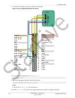
Страница 16: ...e 5 1 Connect Sense Hat B to the 40 Pin Header 40 Pin GPIO Header Sense HAT B Pin Number Pin Name 3V3 1 3 3V Power GND 9 GND SDA 3 GPIO58 I2C SDA SCL 5 GPIO57 I2C SCL Figure 5 1 Connect Sense Hat B to the 40 Pin GPIO Header 1 3 5 7 9 11 13 15 2 4 6 8 10 12 14 16 5V Power 5V Power GND GPIO5 UART TX GPIO6 UART RX GPIO38 GND GPIO21 3 3V Power GPIO58 I2C SDA GPIO57 I2C SCL GPIO55 GND GPIO42 GPIO43 GPI...

Страница 17: ...r is the number indicated in the Pin Name For more details about the GPIO Pin Name see the GPIO Pinout on page 9 in this document The pin names of the I2C GPIO are listed as follows GPIO58 I2C SDA GPIO57 I2C SCL 5 2 Debugging I2C GPIO Perform the following steps to debug I2C 1 Execute the following command to scan the bus i2cdetect l Result Figure 5 3 Example Output 2 Execute the following command...

Страница 18: ...vice address 0x0f Memory address Result Figure 5 5 Example Output The register content is 0xb1 in this output 4 Execute the following command to write register data i2cset y 0 0x5c 0x11 0x10 Tip 0 I2C bus number 0x5c I2C device address 0x11 Memory address 0x10 The content to be written in the register 5 Execute the following to read all register values i2cdump y 0 0x5c www starfivetech com 2018 20...

Страница 19: ... 5 I2C Operations Tip 0 I2C bus number 0x5c I2C device address Result Figure 5 6 Example Output 19 2018 2022 StarFive Technology All rights reserved www starfivetech com S t a r F i v e ...

Страница 20: ... GPIO number is the number indicated in the Pin Name For more details about the GPIO Pin Name see the GPIO Pinout on page 9 in this document You can configure the unoccupied pins The following are the default settings in the jh7110 visionfive v2 dtsi Figure 6 1 Modify Pins 6 2 Debugging SPI GPIO This section provides steps for loopback test and testing SPI with the ADXL345 module www starfivetech ...

Страница 21: ...ARCH riscv Result The output file is spidev_test in the same directory 4 Upload spidev_test to VisionFive 2 and change the execution permission by executing the following chmod x spidev_test 5 Confirm the SPI device ls dev spidev Result Figure 6 3 Example Output In this output spidev1 0 is the device name 6 Execute the following command to perform the test spidev_test D dev spidev1 0 v p string_to...

Страница 22: ...e TX and RX output are the same which indicates the test is successful 6 2 2 Testing SPI with ADXL345 Module Perform the following steps to test SPI with the ADXL345 module www starfivetech com 2018 2022 StarFive Technology All rights reserved 22 S t a r F i v e ...

Страница 23: ... I2C SCL GPIO55 GND GPIO42 3 3V Power GPIO52 SPI MOSI GPIO48 SPI SCLK GPIO45 GPIO39 GPIO63 GPIO43 GPIO47 GPIO53 SPI MISO GND GPIO37 GPIO59 PWM1 GPIO60 GND CS SCLK MOSI GPIO 5V GND 3V3 MISO ADXL345 2 Locate to the following path for test tool spidev_test c cd linux tools spi 3 Execute the following command under the test tool directory make CROSS_COMPILE riscv64 linux gnu ARCH riscv Result The outp...

Страница 24: ... following to read the value for multiple registers spidev_test H O D dev spidev1 0 v p xec x00 x00 x00 x00 x00 x00 8 Execute the following to read spidev_test H O D dev spidev1 0 v p x9e x00 9 Execute the following to write spidev_test H O D dev spidev1 0 v p x1e xaa 10 Execute the following to read the verification spidev_test H O D dev spidev1 0 v p x9e x00 www starfivetech com 2018 2022 StarFi...

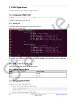
Страница 25: ...umber contained in the Pin Name For more details about the GPIO Pin Name see the GPIO Pinout on page 9 in this document 7 1 2 PWM and Pin Name Mapping The following table describes the PWM and pin name mapping Table 7 1 PWM and Pin Name Mapping PWM GPIO Pin Name PWM0 GPIO46 PWM1 GPIO59 7 2 Debugging PWM GPIO This section describes how to debug PWM GPIO 1 Execute the following to configure the PWM ...

Страница 26: ...ycle echo 1000000 duty_cycle 4 Use an oscilloscope to measure the corresponding pin and check the PWM period and duty cycle Note A duty cycle is the fraction of one period in which a signal or system is active www starfivetech com 2018 2022 StarFive Technology All rights reserved 26 S t a r F i v e ...

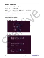
Страница 27: ...contained in the Pin Name For more details about the GPIO Pin Name see the GPIO Pinout on page 9 in this document 8 1 1 Modifying dts To modify dts file perform the following steps 1 Add aliases of uart1 or uart2 on the aliases node The following is an example Figure 8 1 Example Configuration 2 Add uart1 or uart2 node on the dts The following is an example Figure 8 2 Example Configuration 27 2018 ...

Страница 28: ...ame see the GPIO Pinout on page 9 in this document Figure 8 3 Example Configuration 8 1 1 1 UART and DEV Mapping The following table describes the UART and DEV mapping Table 8 1 UART and DEV Mapping UART DEV UART1 dev ttyS1 UART2 dev ttyS2 8 2 Debugging UART GPIO 8 2 1 Hardware Setup To set up the hardware perform the following steps www starfivetech com 2018 2022 StarFive Technology All rights re...

Страница 29: ...GPIO56 GND GND GPIO61 GPIO44 3 3V Power GPIO58 I2C SDA GPIO57 I2C SCL GPIO55 GND GPIO42 3 3V Power GPIO52 SPI MOSI GPIO48 SPI SCLK GPIO45 GPIO39 GPIO63 GPIO43 GPIO47 GPIO53 SPI MISO GND GPIO37 GPIO59 PWM1 GPIO60 GND 3Y3 RXD GND 5V TXD 3Y3 RXD GND 5V TXD IC 2 Connect the other end of the USB to Serial Converter to your device Windows Mac Linux 8 2 2 Debugging UART Send and Receive Functions 1 Confi...

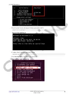
Страница 30: ...nicom o D dev ttyS1 Figure 8 7 Example Output 4 Configure Ubuntu minicom by typing the following sudo minicom s 5 Select Serial port setup and configure minicom as follows Figure 8 8 Example Configuration www starfivetech com 2018 2022 StarFive Technology All rights reserved 30 S t a r F i v e ...

Страница 31: ...d by command dmesg grep tty on Ubuntu Figure 8 10 Example Command and Output 6 Start Ubuntu minicom you can see as follows Figure 8 11 Example Output Test UART Send 31 2018 2022 StarFive Technology All rights reserved www starfivetech com S t a r F i v e ...

Страница 32: ...om interface Figure on the Right VisionFive 2 minicom interface Test UART Receive 8 To test UART receive you can input characters such as hello visionfive on the Ubuntu minicom Then you will see the characters are outputted on the VisionFive 2 minicom Figure 8 13 Test UART Receive Figure on the Left Ubuntu minicom interface Figure on the Right VisionFive 2 minicom interface www starfivetech com 20...

Страница 33: ...p The following table and figure describe how to connect Sense HAT to the 40 pin header Table 9 1 Connect Sense Hat B to the 40 Pin Header Sense HAT B Pin Number 3V3 1 GND 9 SDA 3 SCL 5 Figure 9 1 Connect Sense Hat B to the 40 Pin Header 1 3 5 7 9 11 13 15 2 4 6 8 10 12 14 16 5V Power 5V Power GND GPIO5 UART TX GPIO6 UART RX GPIO38 GND GPIO21 3 3V Power GPIO58 I2C SDA GPIO57 I2C SCL GPIO55 GND GPI...

Страница 34: ...as been installed 3 Execute the following to compile riscv64 linux gnu gcc SHTC3_dev c o shtc3 Result The output file is shtc3 in the same directory 4 Copy the executable code from the shtc3 file to the board and change the execution permission by executing the following command chmod x shtc3 5 Execute the following command to run shtc3 Result The following output indicates the execution is succes...

Страница 35: ...r the detailed specifications refer to the following https www waveshare com wiki 2 4inch_LCD_Module Note The official examples are required to be modified for this demo 9 2 1 Hardware Setup The following table and figure describe how to connect the 2 4inch LCD module with the 40 pin header Table 9 2 Connect 2 4inch LCD with 40 pin Header 2 4inch LCD Module Pin Number VCC 17 GND 39 DIN 19 CLK 23 C...

Страница 36: ...RX GPIO38 GPIO51 GND GPIO49 SPI CE0 GPIO40 GPIO46 PWM0 GPIO36 GND GPIO54 GPIO50 GPIO56 GND GND GPIO61 GPIO44 3 3V Power GPIO58 I2C SDA GPIO57 I2C SCL GPIO55 GND GPIO42 3 3V Power GPIO52 SPI MOSI GPIO48 SPI SCLK GPIO45 GPIO39 GPIO63 GPIO43 GPIO47 GPIO53 SPI MISO GND GPIO37 GPIO59 PWM1 GPIO60 GND VCC GND CLK CS BL DC RST 2 4inch LCD Module DIN www starfivetech com 2018 2022 StarFive Technology All r...

Страница 37: ...ng command to copy the code to the board For example VisionFive 2 tar xvf LCD_Demo tar gz cd visionfive2 main 2 4 Result The following two figures will be displayed in turn One is the photo of VisionFive 2 the other is the official example figure Figure 9 5 Example Output 37 2018 2022 StarFive Technology All rights reserved www starfivetech com S t a r F i v e ...

Отзывы: