background image

Содержание gemini-10X

Страница 1: ...DOT MATRIX PRINTER gemini 10X USERS MANUAL PRELIMINARY ...

Страница 2: ......

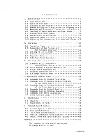
Страница 3: ...nal Character Set 28 3 2 Block Graphic Special Character Set 30 3 3 Italic ASCII Character Set 31 3 4 Download Character Set 32 3 5 Bit Image Graphics Mode 34 4 Functional Control Codes 36 4 1 Commands Used to Control Print Style 36 4 2 Commands Used to Control Vertical Position of the Print Head 42 4 3 Commands Used to Control Horizontal Position of the Print Head 47 4 4 Commands Vsed to Control ...

Страница 4: ...x p l ease confirm that t he f ollowing accessori es and consumab l es ar e in t he box 1 Printer 6 Holder Shaft 2 Prin t er Cover 7 I nk Ribbon 3 Paper Guide 8 Spare Fuse 4 Paper Separator 9 User s Manual 5 Roll Paper Holder 0 Warr anty Car d Fig 1 1 Packing Lis t 1 ...

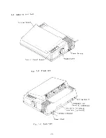
Страница 5: ... 2 Names of Each Part Printer Fig 1 2 Front View Fig 1 3 Back View 2 r Switch Platen Knob DIP Switch 2 Connector for Parallel Interface Port Hole for Serial Interface optional Ground Terminal Power Cord ...

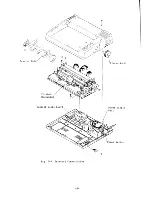
Страница 6: ...Control Logic Board Fig 1 4 Internal Construction 3 Platen Knob Power Supply Unit ...

Страница 7: ...ces 3 Do not operate the printer under circumstances of extreme high or low temperature or of strong vibration 4 Do not operate the printer in a place of high humidity or a dusty place with oil or iron particles 5 Provide a separate power supply away from applicances or noise generating motors 6 Power supply voltage shall be the same voltage as specified on the identification plate Extremely high ...

Страница 8: ...ter remove packing and screws with the following procedures Please keep packing and screws if necessary for further printer shipping 1 Place the Gemini printer upside down on a soft material like a foam rubber cushion 2 Remove two screws with screwdriver as illustrated in Fig 1 5 Printer Lower Case Fig 1 5 Removing Fixing Screws for Shipping 3 Return the printer to its original position 4 Lift the...

Страница 9: ... 5 Remove the packing material from inside of the printer as shown in Fig 1 6 Platen Jamb Packing for Print Head Print Head Platen Jamb Fig 1 6 Removing Packing 6 ...

Страница 10: ...e snap levers by comparing your printer with the Gemini shown in Fig 1 7 4 Pull both snap levers forward the one on the right and the one on the left of the tractor unit and at the same time 5 Rock the tractor unit up and back about a half inch The tractor unit rests On two stoppers just above the right and left ends of the platen This step in removing the tractor is done by simply rocking the uni...

Страница 11: ...e left and right to the stoppers of the printer as shown in Fig 1 8 2 Push the tractor unit slightly downward it then fits in properly to the hooks shown B which are provided at the end of the snap levers to clamp lever shafts Tractor Unit Clamp Lever Fig 1 8 Mounting Tractor Unit 8 ...

Страница 12: ...r feed To insert the paper se arator and paper guide insert one side to the hole of printer then gently bend back the other protruding end until it slips into place Make sure you do not get these racks in upside down Paper Upper Cas Printer Fig 1 9 Mounting of Paper Separator Paper Guide 9 Guide ...

Страница 13: ...the printer Insert the hooks of the roll paper holder to the holes which are provided at the back side of the printer Fig 1 10 Setting Roll Paper Holder 2 Insert roll paper onto holder shaft Pay attention to winding direction of the roll paper Roll Holder Shaft paper l Fig 1 11 Setting Holder Shaft 10 ...

Страница 14: ...lace the roll paper with shaft to the roll paper holder as shown in Fig 1 12 Check that the unwinding direction of the roll paper is correct Roll Paper IHolder Shaft Fig 1 12 Setting Roll Paper to Holder 11 ...

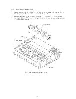
Страница 15: ...pool Fig 1 13 Pathway of Ink Ribbon 4 Then thread the ribbon taking care around the print head As shown in Fig 1 14 you might want to use a ball point pen to lightly press the ribhon guide towards the platen while inserting the ribbon in the slot between the print head and the ribbon guide Fig 1 14 shows you how to position the ribbon to avoid misprints or the ribbon coming off during printing Two...

Страница 16: ...et 6 Set the other ribbon spool on the opposite spool axis making sure the drive pins are engaged 7 When the ribbon threading has been accomplished turn the ink ribbon spools by hand maybe four or five rotations of the spools This verifies that everything was done properly and that the ribbon is smoothly fed Note As shown in Fig 1 16 you can turn the ribbon over and use the other side when it star...

Страница 17: ...ease Lever 0 Y 0 e A L f fI c 1 j Single Sheet Paper z Paper Chute Fig Single Sheet Paper Set 5 Adjust the paper horizontally right and left so that the sheet is where you want it Make sure the area you are going to print on the sheet is within the margins you are going to set for the print out 6 Make sure the paper is in straight 7 Position the sheet of paper where you want the first line of text...

Страница 18: ...letter T S Lift up the paper press 6 Pull the paper separator upright as shown in Fig 1 19 The paper guide should remain horizontal 7 Insert the roll paper as shown in Fig 1 19 so that when viewed from the printer s right side the paper will unroll in a clockwise direction Paper Separator Release Lever Paper Press Fig 1 19 Setting Roll Paper Roll Paper Paper Holder 8 As shown in Fig 1 20 unroll so...

Страница 19: ...en push the release lever back to the locked or closed position marked with the letter F 12 Lower the paper separator as shown in Fig 1 21 Fig 1 21 Adjusting Roll Paper 13 Rotate the platen knob and check to see if the roll paper is feeding smoothly If some adjustment is needed pull the release lever forward to the open mode again and adjust the placement of the paper before closing the release le...

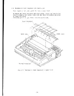
Страница 20: ...ehind the printer aper Guide 8 Pick up the top sheet of paper and feed it between the paper chute and platen cover from the back side of the platen 9 Push the paper down and forward so it wraps around the platen 10 Return the paper separator to its original position 11 Open the tractor covers atop the right and left sprocket mechanism as shown in Fig 1 23 12 Pull the paper up past the sprocket mec...

Страница 21: ...n knob and roll the paper up or down until the correct print start position is obtained Clamp Lever Fig 1 24 Adjusting Sprocket Paper 17 When the paper installation is completed replace the printer cover and turn the power on Note If you use multi layer paper such as a three sheet carbonless form with this printer you ll adjust the print gap as discussed in section 1 10 18 ...

Страница 22: ...25 Pulling the adjust lever forward will widen the gap and pushing it backwards will make the print head gap narrower There are five positions that can be attained by moving the lever to different adjustments These five positions are caused by the control arm resting in different notches as shown in Fig 1 25 The second step is most commonly used for single sheets of paper Release Lever Fig 1 25 Ga...

Страница 23: ... lamp is green and glows hen data tran smission is possible During transmission the lamp flickers The red lamp of PAPER OUT means jus t that your prin ter is out of paper and has stopped printing The ON LINE button lets you alter the printer status between being local which means independent and on its own and on line which means able to receive data transmitted from a computer When you turn the p...

Страница 24: ...nt the connecting plug from being disconnected Fig 2 3 Connection with Interface Conditions for interface cable 1 Connecting plug 57 30360 AMPHENOL product 2 Connecting cable Connector for Parallel Interface It is recommended to use a cable meeting the following conditions a Use a twisted pair cable whose length is shortest within the necessary range b Connect the return side of the twisted pair c...

Страница 25: ...d on the control logic board One of the DIP switches can be set at the rear of the printer however in case of another switch it is necessary to disassemble the upper case When you need to disassemble the upper case please refer to section 5 2 1 DIP Switch 1 Interface Connector Fig 2 4 DIP Switches on Control Logic Board 22 ...

Страница 26: ...Set Refer below ON 1 5 Line Feed Value 1 6 inch 1 8 inch ON 1 6 ON 1 7 Selection of International Refer below Character Set and Form ON 1 8 Length ON Selection of Character Set DIP Switch Pin No Character Set 1 1 1 4 ON ON Standard ASCII Character Set ON OFF Download Character Set OFF ON Italic ASCII Character Set OFF OFF Italic ASCII Character Set Selection of International Character Set and Form...

Страница 27: ...ter mechanism to the computer Disables the printer when paper out CR code is ignored and print data of one line is stored in the buffer until the memory is full or by input of a LF code Interface is set to 7 bits Automatic line feed is performed by input of CR code OFF Paper out signal is not transmitted from the printer mechanism to the computer Enables the printer to print with no paper Printing...

Страница 28: ...code to Gemini as dis cussed in section 4 7 hen the initialization is done the following is accomplished a The print head goes to its home position except with ESC b The buffer contents are cleared c The characters in download chClracter RAN are cleared except with ESC d Character pitch is set to 10 CPI or 17 CPI according to the DIP switch 1 3 e Line pitch is set to 1 6 inch or 1 8 inch according...

Страница 29: ...rridden or released temporarily by control code ESC 8 or ESC 9 refer to section 4 7 _ _l_ c Frlntln 9 ample l ruc kbel Diel c o c x o Po Po 4 J L ____ Detection Position lJ 6 mm 164 mm I J Center of Printer Fig 2 6 Paper Out Detection Position 2 6 Self Test Print Function Self test print function is pre programmed in the Gemini printer With this function the following tests are accomplished 1 Prin...

Страница 30: ...ter patterns desired Selection of Standard Character ROM and Download Character RAM are shown in Fig 3 1 1 l I I I I L I Italic ASCII Character Set I ESC 4 ESC 5 Standard ASCII I I Character Set Block Graphic Including Special Character International Set Character Set r ESC 1 ESC a Character ROM Download Character Set RAN Fig 3 1 Selection of Character Sets 27 ...

Страница 31: ...aracter Set is shown in Fig 3 2 Besides it is possible for the portion there of indicated by frame to be converted to the International Character Set by setting of DIP switches and or control codes as shown in Fig 3 3 5 6 p 1112 113 r 4 Fig 3 2 Data Code List of Standard ASCII Character Set 28 ...

Страница 32: ...Fig 3 3 Data Code List of International Character Set 29 ...

Страница 33: ...3 2 Block Graphic Special Character Set Data code list of block graphic and special character set is shown in Fig 3 4 Fig 3 4 Data Code List of Block Graphic Special Character Set 30 ...

Страница 34: ...haracter Set Data code list of Italic ASCII Character Set is shown in Fig 3 5 This character set can be selected by setting of the DIP switch or control code ESC 4 Fig 3 5 Data Code List of Italic ASCII Character Set 31 ...

Страница 35: ...efine the Download Character character patterns are inputted into the RAM after transmitting the ESC 1 code designating the position to be written and decender data of these characters As setting of Download Characters can be possible up to the number of 8 pins vertical x 9 pins horizontal it is necessary upon printing these characters to designate whether they are to be shifted by one dot down or...

Страница 36: ...ed to be printed then characters so defined are printed by Gemini Download characters can not be mixed on the same line as other character sets When download character set is set for a particular line all characters printed on that line will be from the download RAM If normal character set is selected for when selected for download character before a line feed all characters in that line will be p...

Страница 37: ...0 dots per inch with Double Speed Quadruple density ESC z n n2 ro ro2 240 dots per inch How to Obtain n and n2 It is necessary to send the number of data by n n2 in decimal numbers or hexadecimal numbers following the ESC K ESC L ESC y or ESC z The number of columns to be printed is given by n 256 n2 The maximun number of columns is shown below Type of Bit Image Graphics Mode Normal density Dual d...

Страница 38: ...ume that data are given as follows 0 0 11011 1 I 0 0 1 0 0 1 1 1 0 0 110 1111 Example A Example B where a box with denotes the bit 1 and a blank box denoted the bit 0 According to the chart in Appendix you can define 00100100 in binary as 24 in hexadecimal 36 in decimal for the example A and 01010101 in binary as 55 in hexadecimal 85 in decimal for the example B As you can see the first 4 bits are...

Страница 39: ...print mode and special effects 1 Font Style Controls CODE ESC 5 PURPOSE FORMAT REMARKS REFERENCE CODE ESC 4 PURPOSE FORMAT REMARKS REFERENCE CODE ESC 7 n PURPOSE FORMAT REMARKS Select the standard ASCII character set CHR 27 CHR S3 This command causes the printer to cancel the italic ASCII character set and select the standard ASCII character set ESC 4 Select the italic ASCII character set CHR 27 C...

Страница 40: ...This command is cancelled by the transmission of the ESC B 1 code or ESC B 3 code or S1 code or DC2 code ESC B 1 ESC B 3 DC2 S1 ESC SI Set the print pitch to Condensed print mode CHR 27 CHR 66 CHR 3 After this command is set to the printer subsequent printing is done in Condensed print mode 17 characters per inch The number of print columns per line is 136 This command is cancelled by the transmis...

Страница 41: ...HR 87 CRR O This command cancels the Enlarged mode set by ESC W1 code or SO code and set in the normal mode 10 CPl 12 cpr and 17 Cpr ESC W 1 SO ESC so DC4 Cause the printer to print in Enlarged mode CRRS 14 A single character command to cause the printer set in Enlarged mode This command is cancelled by the transmission of the ESC W 0 code or DC4 code or CR code or at the end of one line of print ...

Страница 42: ...trike printing mode can be used with any other print style commands ESC H Cancel the Double strike printing mode CHR 27 CHR 72 When ESC H code is transmitted to the printer subsequent characters are printed in the normal mode ESC G Print in Emphasized printing mode CHR 27 CHR 69 When ESC E code is sent to the printer all subsequent characters are printed in the Emphasized print mode The Emphasized...

Страница 43: ...s are printed in superscript mode While in superscript the normal bi directional print mode is cancellad and the uni directional print mode is invoked Superscripts may be used with the italic font and in pica elite and condensed pitches They may not be used in enlarged print mode or with emphasized printing mode Superscripts are always printed in double strike Superscript mode is cancelled by send...

Страница 44: ...ing mode This mode is invoked by the super subscript mode and by the graphics mode Uni directional printing is useful in printing tables and charts and ensures that columnar numbers and other characters are in alignment ESC C 0 ESC S 1 ESC S 0 Print in bi directional printing mode CHR 27 CHR 85 CHR O The ESC U 0 code is sent to the printer to cancel uni directional printing and return to the faste...

Страница 45: ... DIP switch 2 4 is on a line feed is automatically generated when the printer receives a CR code ESC 0 ESC 1 ESC 2 ESC A n ESC 3 n ESC J n Change the line feed to 1 8 inch CHR 27 CHR 48 When ESC 0 code is sent to the printer successive line feeds are set to 1 8 inch ESC 1 ESC 2 ESC A n ESC 3 n ESC J n Change the line feed to 7 72 inches CHR 27 CHR 49 When ESC 1 code is sent to the printer successi...

Страница 46: ...re set to n 144 inches The value of n must be between 1 and 127 ESC 0 ESC 1 ESC 2 ESC A n ESC J n Send a one time only line feed of n 144 inches CHR 27 CHR 74 CHR n When this code is sent to the printer it causes the paper to be advanced by n 144 inches The value of n must be between 1 and 127 This command does not change the size of the existing line feed value ESC 0 ESC 1 ESC 2 ESC A n ESC 3 n 4...

Страница 47: ...f the page is set to n lines The value of n must be between 1 and 127 ESC COn Change the setting of the form length to n inches CHR 27 CHR 67 CHR O CHR n When this code is received the length of the page is set to n inches The value of n must be between 1 and 32 ESC C n Change the line location of the header first line of the form CHR 27 CHR 82 CHR n This command is used to change the location of ...

Страница 48: ...ERENCE Cancel the skip over perforation feature CHR 27 CHR 79 When this command is received the skip over perforation set by ESC N n code and the line location of the header of the form set by ESC R n code are cancelled ESC N n ESC R n 45 ...

Страница 49: ... the positions of the vertical tabs CHR 27 CHR 80 CHR nj CHR n2 CHR O When this command is sent to the printer the existing vertical tab positions are canceilled The new vertical tabs are set to lines nj n2 etc The maximum number of vertical tabs is 20 The NUL CHR O character is used to end the command The value of n must be between 1 and 255 and nj should be less than n2 n2 less than n3 etc VT Se...

Страница 50: ... print margin CHR 27 CHR 77 CHR n After this command is sent to the printer successive carriage return codes will cause the print head to return to the n print position The value of n must be between 1 and 255 The maximum number of print positions on an 8 inch wide form is 80 for 10 cpr characters 96 for 12 CPI and 136 for 17 CPl CR LF ESC Q n Set the right hand print margin CHR 27 CHR 81 CHRS n A...

Страница 51: ...ss than n3 etc REFERENCE HT CODE ESC b n PURPOSE FORMAT REMARKS REFERENCE CODE BS PURPOSE FORMAT REMARKS REFERENCE Send a one time only horizontal tab of n columns CHR 27 CHR 98 CHR n When this command is sent to the printer the print head is shifted n columns to the right The value of n must be between 1 and 127 This command does not change the preset horizontal tab positions ESC D nj nZ NUL HT M...

Страница 52: ...racters determine which pins are fired according to the following format ESC K n nZ mj mZ ESC z nj nZ mj mZ ESC Y nj n2 mj mZ CODE ESC Y nj nZ mj m2 PURPOSE FORMAT REMARKS REFERENCE Print Dual density graphics with double speed CHR 27 CHR 121 CHR nj CHR nZ CHR mj CHR mZ This command selects the 120 dots per inch column scan bit image graphics mode with double speed The number of columns to be prin...

Страница 53: ...ender data The value of nj must be between 32 and 126 The value of nz must be 1 when the character is shifted one dot downward and 0 when it is not shifted ESC 0 ESC 1 ESC 0 Copy the fonts in Character ROM into Download RAM CHR 27 CHR 42 CHR O When this command is received the fonts in Character ROM are copied into the Download Character RAM ESC 1 nj nz mj mz ESC 1 ESC 0 Select the download charac...

Страница 54: ...s sent to the printer the existing macro instruction is cancelled The new macro instruction is set The maximum number of instruction bytes is 16 The RS CHR 30 1 character is used to end the command REFERENCE ESC CODE ESC PURPOSE FORMAT REMARKS REFERENCE Select the macro instruction CHR 27 CHR 33 When this code is sent to the printer the macro instruction set by ESC RS code is selected ESC RS 51 ...

Страница 55: ...7 CHR 6l This command is used to control the value of the eighth bit of the data that is sent to the printer After this command is received by the printer all subse quent data is processed with the 8th bit regarded as set to O This code should not be used to transmit printer function code The ESC II code is used to cancel this command ESC II ESC Accept eighth bit as is from computer CHR 27 CHR 35 ...

Страница 56: ...ENCE Put printer in on line mode CHR l7 en this code is sent to the printer the DC3 code is cancelled and puts the printer back on line mode DC3 Activate the Gemini buzzer CHR 7 When this code is sent to the printer the result is that the built in buzzer beeps for one fourth second The buzzer function can be temporarily deactivated by sending an ESC Y 0 to the printer ESC Y 0 ESC Y 1 Disable the B...

Страница 57: ...single sheet If the paper out signal were not disregarded the printer would stop printing part of the way down the single sheet because the printer would think its out of paper ESC 9 Regard the signal from the paper out detector CHR 27 CHR 57 When this code is sent to the printer the signal from the paper out detector is restored ESC 8 Initialize the printer conditions CHR 27 CHR 64 When this code...

Страница 58: ... Remove dirt and dust from the case and cover of the printer by using a soft cloth with alcohol Note Be careful so as not to moisten electronics parts and or the printer mechanism 2 Remove dust and small particles from the printer mechanism and PCB by means of a soft brush or the like Note Be careful to prevent damage to electronic parts and wiring 55 ...

Страница 59: ... other parts in the printer it is necessary to remove the upper case of the printer 1 Turn off the power switch and unplug the power plug from the power receptacle 2 Extract the platen knob from the printer body 3 Remove the two mounting screws from the upper case and disassemle the upper case Knob Fig 5 1 Removal of Upper Case 56 ...

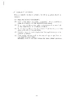
Страница 60: ...e fuse 1 Remove the upper case of the printer as described in section 5 2 1 2 Check the fuse on the fuse board near the power switch 3 If the fuse is blown replace it with a 1 25A 125V slow blow type fuse 4 After check and replacement of the fuse have been completed reassemble the upper case etc in the reverse procedures as before Lower Case Fuse Board Power Switch Fig 5 2 Replacement of Fuse 57 ...

Страница 61: ...rs fastening the print head 4 Install a new print head and fasten it with fastening screws and washers Clamping torque should be 3 kg cm and apply screw lock to the screw heads 5 Insert the head cable into the head connector If this connection is loose it may cause print problems WARNING The print head will be hot during operation and soon afterwards so be careful not to burn yourself Print Head H...

Страница 62: ...ix Quadruple density 7 or 8 1920 dot matrix Standard characters Bi directional printing with logic seeking Graphics mode Uni directional printing 80 96 136 characters Enlarged characters 40 48 68 characters 120 characters per second CPS 96 Standard ASCII character 88 International character Selectable 96 Italic ASCII character 64 Special character 32 Block graphic character 96 Download character P...

Страница 63: ...E E OJ s c rl 00 I I ___J II rr r i I C I 0 392 mID 15 2 inches tel 0 Fig 6 1 External Dimensions 60 ...


Страница 64: ...1 _ _ _ _ _ _ _ _ _ _ _ _ _ 1 r i I I FIFO lnpu t Buffer I I _B_o r J P t o __ J I JAC Power Fig 6 2 Block Diagram of Gemini lOX Printer Parallel Interface I r L _ _ _ _ _ I I FIFO Inpu t I _ Buffer __ _ I I I Se ri l I optional I r _J L Interface I I I optional Control CPU L ________ L _ _ J Head Vriver Motor Driver Sensors Fig_ 6 3 Block Diagram of Control Logic Board 61 ...

Страница 65: ...x 13 cm 5 inches 3 sheets 1 original and 2 carbonless copies 7 5 25 4 cm 3 10 inches 0 07 00 1 mm 1 363 0 1 254 inch 1 part 0 28 mm 1 91 incn 3 parts 6 3 Ink Ribbon Specifications ITEM Color Ribbon Material Dimensions Spool Standard Recommended Product SPECIFI CATIONS Black single color Nylon 1140 13 mm W x 10 5 m L 1 2 inch x 11 5 yards Eyelets are provided near both ends Underwood s Plastic Type...

Страница 66: ... BUSY signals Refer to Fig 6 4 Logic Level Compatible with TTL level Refer to Fig 6 5 Connector Signals Refer to section 6 4 2 ACK DATA BUSY I r Approx I I i jtr ITU r t __________ Ir T More than 0 5wsec Fig 6 4 Data Transfer Timing Chart Signal Name Circuit Example DATA 1 DATA 8 To Printer 4 7k 4 7krl STROBE 100 2 To Printer 470pF J BUSY ACK 4 7krl From Printer Fig 6 5 Circuit Example of Parallel...

Страница 67: ...gic is 1 the signal level is high when 0 the signal level is low A signal with a pulse width of approx 5 sec generated after the data is received When this signal has been completed the next data acceptance is permitted A signal at DC level which indicates the operating condition of the printer When this signal level goes low the next data acceptance is permitted A signal at DC level which indicat...

Страница 68: ... pins and its _________ RE_T_U_RN __ P_I_N __l_O_ ______________________ relevant signal pin 29 30 TWISTED PAIR RETURN PIN 11 TWISTED PAIR RETURN PIN 12 31 INPUT PRIME 32 ERROR 33 EAl GND 34 NC 35 NC 36 NC IN OUT BUSY PAPER END A signal for resetting the control circuit When this signal level goes low the printer is initialized and the memory buffer is cleared This signal level goes low when the p...

Страница 69: ...Rate Word Length Start Bit Data Bit Parity Bit Stop Bit Signal Polarity Mark Space Handshaking SPECIFICATIONS Asynchronous Simplified Serial Version 110 9 600 bit per second BPS Selectable Buffered Serial Version 110 19 200 BPS Selectable 1 bit 7 or 8 bits Selectable Odd Even or None Selectable 1 or 2 bit length Logic 1 3V 15V Logic 0 3V 15V Simplified Serial Version 1 Byte Serial Busy Mode Buffer...

Страница 70: ... 21 00010101 15 74 01001010 4A 22 00010110 16 75 01001011 4B 23 00010111 17 76 01001100 4C 24 00011000 18 77 01001101 4D 25 00011001 19 78 01001110 4E 26 00011010 1A 79 01001111 4F 27 00011011 IB 80 01010000 50 28 00011100 lC 81 01010001 51 29 00011101 ID 82 01010010 52 30 00011110 lE 83 01010011 53 31 00011111 IF 84 01010100 54 32 00100000 20 85 01010101 55 33 00100001 21 86 01010110 56 34 001000...

Страница 71: ...30 10000010 82 186 10111010 BA 131 10000011 83 187 10111011 BB 132 10000100 84 188 10111100 BC 133 10000101 85 189 10111101 BD 134 10000110 86 190 10111110 BE 135 10000111 87 191 10111111 BF 136 10001000 88 192 11000000 CO 137 10001001 89 193 11000001 C1 138 10001010 8A 194 11000010 C2 139 10001011 8B 195 11000011 C3 140 10001100 8e 196 11000100 C4 141 10001101 8D 197 11000101 C5 142 10001110 8E 1...

Страница 72: ...5 230 11100110 E6 231 11100111 E7 232 11101000 E8 233 11101001 E9 234 11101010 EA 235 11101011 EB 236 11101100 EC 237 11101101 ED 238 11101110 EE 239 11101111 EF 240 11110000 FO 241 11110001 Fl 242 11110010 F2 243 11110011 F3 244 11110100 F4 245 11110101 F5 246 11110110 F6 247 11110111 F7 248 11111000 F8 249 11111001 F9 250 11111010 FA 251 11111011 FE 252 11111100 FC 253 11111101 FD 254 11111110 F...

Страница 73: ...uter Cancel the download character set Select the download character set Copy the fonts in Character ROM into Download RAM Define the download character into RAM Define the macro instruction Cancel the underline mode Print characters with underline Change the line feed to 1 8 inch Change the line feed to 7 72 inches Change the line feed to 1 6 inch Change the line feed to n 144 inches Select the i...

Страница 74: ...ver perforation feature 45 Change the positions of the vertical tabs 46 Set the right hand print margin 47 Change the line location of the header of the form 44 Print in superscript mode 40 Print in subscript mode 40 Cancel the super subscript mode 40 Print in bi directional printing mode 41 Print in uni directional printing mode 41 Cause the printer to print in Normal mode 38 Cause the printer to...

Страница 75: ...rference to radio or televi sion reception which can be determined by turning the epuipment off and on the user is encouraged to try to correct the interference bv one or more of the following measures reorient the receiving antenna relocate the computer with respect to the receiver move the computer away from the receiver plug the computer into a different outlet so that computer and receiver are...

Страница 76: ...ORD STAR MICRONICS INC N Y Pan Am Building Suite 2308 200 Park Ave New York NY 10166 212 986 6770 STAR l lICRONICS INC DALLAS Suile 216 ll20 Empire Central Place Dallas TX 75247 214 631 8560 STAR MICRONICS INC CA 3 Oldfield Irvine Ca 92714 714 768 4340 ...

Отзывы: