Programming
Instruction Manual
69
Setup
Users at this level can modify all parameters in the Job area. They may also modify
parameters in the Other area except in the Users, Tool and Stats tabs.
Tool
Users at this level can modify parameters under the Tool tab in the Other area, as well as
set Preventive Maintenance Threshold and reset the PM and Cycle counters in the SERVICE
menu.
Diagnostics
Users at this level can force Inputs or Outputs ON or OFF and REMOVE forces in the I/O
tab of ANALYZE.
Statistics
Users at this level can modify parameters under the Stats tab in the Other area.
Communications
Users at this level can modify all parameters in the Communications area.
Press OK to save.
To delete a user press the MANAGE button and select option 2. Delete. Confirm deletion by pressing OK. This
action requires the Administrator password; once entered, user is deleted.
Import – Users can be entered from a backup file. Connect a USB memory stick to the USB port, scroll to desired
file and press IMPORT. The new users display on the User list.
Export – To backup Users, connect a USB memory stick to the USB port, name the file, then press SAVE.
Press OK to save.
Use the right arrow to move to the next tab or press EXIT to save the changes and return to the Run screen. See
section “3.1.2.6 Exit” on page 52.
3.1.4.3
I/O Tab
Press the BUS interactive menu button then the up/down arrows to select the I/O bus for editing/ viewing. Then
press OK.
The buses available are dependent on the options installed.
3.1.4.3.1
Outputs
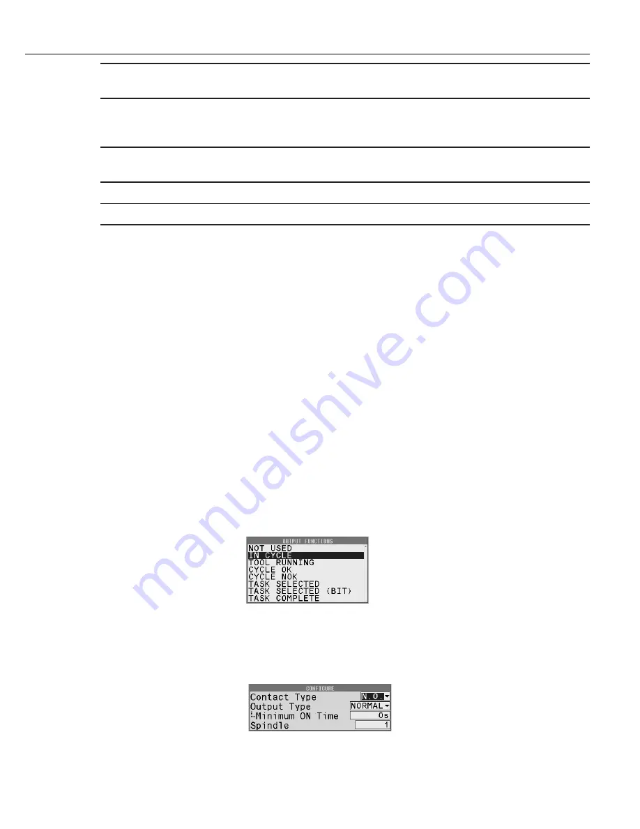
The 24V DC Connector has pins C through K designated as Outputs from the controller. The pin assignments are
selectable on this tab. Use the up/down arrows to select the pin to assign, then press the Toggle button. A list of
available output functions displays. See section “6.12 Assignable Input and Output Functions” on page 120 for
the complete list and descriptions.
Highlight function to assign to the selected pin and press the NEXT button. An Output functions can be assigned
to more than one pin.
The selected Output function must then be configured. See section “6.12.2 Output Descriptions” on page 129
for configuration options and descriptions. After modifying press FINISH.
Содержание QB Expert
Страница 8: ......
Страница 22: ... QB Expert Alpha Controller 14 5 7 8 5 7 6 8 1 2 4 1 3 Mounting QB Alpha Expert Controller onto Plinth ...
Страница 23: ...Introduction Instruction Manual 15 ...
Страница 24: ......
Страница 36: ......
Страница 37: ...3 QB Expert Alpha Controller Programming SETUP Area SERVICE Area ANALYZE Area ...
Страница 94: ......
Страница 109: ...Instruction Manual 101 ...
Страница 110: ......
Страница 123: ...Instruction Manual 115 Tool Operation ...
Страница 124: ......
Страница 132: ...Input and Output Connector QB Expert Alpha Controller 124 Inputs example ...
Страница 133: ...Controller Connections Instruction Manual 125 Outputs Sourcing example ...
Страница 157: ...Controller Connections Instruction Manual 149 ...
Страница 158: ...MODBUS TCP QB Expert Alpha Controller 150 ...
Страница 175: ...Embedded PLC Instruction Manual 167 ...
Страница 176: ......
Страница 177: ...8 QB Expert Alpha Controller Multiple Spindle Connection Disconnect Synchronization Networking ...
Страница 183: ...Multiple Spindle Instruction Manual 175 ...
Страница 184: ... QB Expert Alpha Controller 176 ...
Страница 201: ...Instruction Manual 193 Maintenance ...
Страница 202: ...QB Expert Alpha Controller 194 ...
Страница 203: ...10 QB Expert Alpha Controller Appendix A Torsion Compensation Angle Validation ...
Страница 206: ......
Страница 207: ...11 QB Expert Alpha Controller Glossary ...
Страница 210: ......


