D7418/4-UL
Y04/YL4 INSTALLATION INSTRUCTIONS
General Description: This application should be installed and used as recommended by the National Fire Protection
Association standards and practices.
The Installer should be familiar with these requirements together with any local codes or special requirements of the local
Fire Authority having jurisdiction.
The alarm sounders are intended for connection to the output alarm circuit of a UL listed fire alarm control panel only. All
alarms are compatible with DC line status monitoring. The alarm sounders are suitable for outdoor use (-35ºC to +66ºC).
Installation procedures must confirm to appropriate agency requirements including but not limited to the following:-
NFPA72E, NEC ART.760 ET.AL., CAN/ULC-S524-M86, CEC PART 1 SEC 32
Installation: The sounder or combined sounder strobe units can be affixed to most surfaces using the back box supplied
separately.
Supply input: Ensure that the supply is correct for the voltage rating of the sounder or combined sounder strobe being
installed. Ensure that the supply is OFF before making any connection and wire only in accordance with the terminal label
detail.
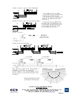
Sound selection: Ensure the supply is OFF before proceeding. All dc and ac units have selectable alarm sounds (see
table below for details) and are selectable by means of a 5 way dil switch SW1. A second sound is made available upon
the application of a third wire connected to terminal TB1/3 as shown in Fig. 1 while still connected to terminal TB1/2.
Alternatively 1st and 2nd stage sound signals can be generated by supply reversal (FOR DC UNITS ONLY) see Fig. 2.
Independent second stage sound is available by using SW2 (OPTIONAL- only fitted with orders).
WARNING - Loud alarm sound. Wear ear defenders when testing, installing and commissioning.
- HIGH VOLTAGES ARE PRESENT WITHIN THE BEACON WHEN OPERATIONAL
SOUND SELECTION TABLE
First Stage Sound
frequency
rept.
Second
switches
Hertz
rate
Stage
1 2 3 4 5
Special Application
1 Alternate two-tone
800-1000
0.5
3
1 1 1 1 1
Fire Alarms
2 Alternate two-tone
2500-3100
0.5
4
0 1 1 1 1
Security Alarms
3 Alternate fast two-tone
800-1000
0.25
7
1 0 1 1 1
Increased urgency
4 Alternate fast two-tone
2500-3100
0.25
8
0 0 1 1 1
Security deterrent
5 Alternate two-tone
440-554
0.4/0.1
14
1 1 0 1 1
AFNOR, France
6 Alternate two-tone
430-470
1.0
14
0 1 0 1 1
7 Alternate v.fast two-tone 800-1000
0.13
12
1 0 0 1 1
8 Alternate v.fast two-tone 2500-3200
0.07
13
0 0 0 1 1
9 Alternate two-tone
440-554
2.0
10
1 1 1 0 1
Turn-out, Sweden
10 Continuous note
700
-
1
0 1 1 0 1
All-clear, Sweden
11 Continuous note
1000
-
31
1 0 1 0 1
12 Continuous note
1000
-
7
0 0 1 0 1
13 Continuous note
2300
-
2
1 1 0 0 1
14 Continuous note
440
-
9
0 1 0 0 1
15 Interrupted tone
1000
2.0
31
1 0 0 0 1
16 Interrupted tone
420
1.25
30
0 0 0 0 1
AS2220, Australia
17 Interrupted tone
1000
0.5
1
1 1 1 1 0
18 Interrupted tone
2500
0.25
4
0 1 1 1 0
19 Interrupted tone
2500
0.5
2
1 0 1 1 0
20 Interrupted tone
700
6/12
10
0 0 1 1 0
Pre-vital mess, Sweden
21 Interrupted tone
1000
1.0
32
1 1 0 1 0
22 Interrupted tone
700
4.0
10
0 1 0 1 0
Air-raid, Sweden
23 Interrupted tone
700
0.25
10
1 0 0 1 0
Local warning, Sweden
24 Interrupted tone
720
0.7/0.3
10
0 0 0 1 0
Industrial alarm, Germany
25 Int,fast,rising volume
1400
0.25
26
1 1 1 0 0
26 Fast siren
250-1200
0.085
11
0 1 1 0 0
27 Rising constant, fall
1000
10/40/10
17
1 0 1 0 0
Industrial alarm, Germany
28 ISO 8201 Evacuation
800-1000
as std
11
0 0 1 0 0
Int’l evacuation alarm
29 Fast whoop
500-1000
0.15
32
1 1 0 0 0
30 Slow whoop
500-1200
4.5
12
0 1 0 0 0
Evacuation, The Netherlands
31 Reverse sweep
1200-500
1
11
1 0 0 0 0
Evacuation, Germany
32 Siren
500-1200
3.0
26
0 0 0 0 0
Switch settings: ON=1 and OFF=0
MOUNTING: The Y04/YL4 series alarm units are supplied separate from the back box. The back box should be mounted
to a suitable surface or to a standard wiring box using any of the mounting holes. 20mm cable entries are provided on all
sides and in the base. To maintain the integrity of the weather seal, the cable entry must be via a suitable sealed gland.


