background image

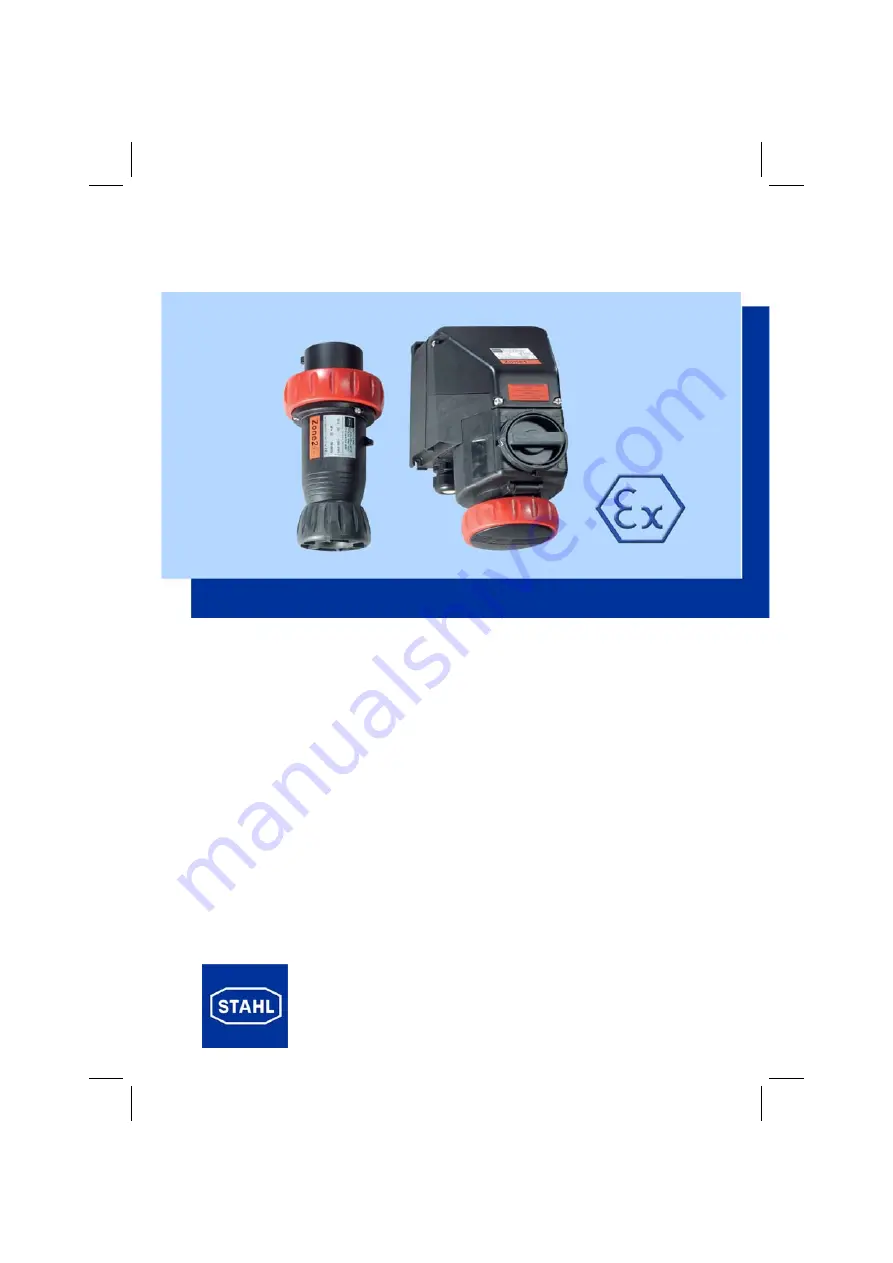
BETRIEBSANLEITUNG

OPERATING INSTRUCTIONS

INSTRUCTIONS DE SERVICE

Wandsteckdose, Stecker

Wall-mounting socket, Plug

Prise murale, Fiche

Typen / Types

7571/11, 7571/12

Содержание 126437

Страница 1: ...BETRIEBSANLEITUNG OPERATING INSTRUCTIONS INSTRUCTIONS DE SERVICE Wandsteckdose Stecker Wall mounting socket Plug Prise murale Fiche Typen Types 7571 11 7571 12 ...

Страница 2: ...ing 20 7 Installation 22 8 Commissioning operation 25 9 Servicing 26 10 Transport and storage 27 11 Disposal 27 SOMMAIRE 1 Symboles 29 2 Consignes de sécurité 29 3 Conformité aux normes 30 4 Fonction 30 5 Caractéristiques techniques 30 6 Disposition et montage 34 7 Installation 36 8 Mise en service fonctionnement 39 9 Maintenance 40 10 Transport et stockage 41 11 Réglementation concernant les déch...

Страница 3: ...Angaben dieser Betriebsanleitung die Kennwerte und Bemessungsbetriebsbedingungen der Typ und Daten schilder zusätzliche Hinweisschilder auf dem Gerät dass Beschädigungen des Gerätes den Ex Schutz aufheben können dass vor dem Öffnen des Gerätes die Spannungsversorgung unterbrochen werden muss dass bei gezogenem Stecker der Klappdeckel der Steckdose mit dem Bajonettring verschlossen ist dass nach je...

Страница 4: ...e elektrische Betriebsmittel Sie dienen zum Anschluss ortsveränderlicher und ortsfester elektrischer Betriebsmittel sowie zur Verbindung von Leitungen bzw Strom kreisen in explosionsgefährdeten Bereichen 5 Technische Daten Bei abweichenden Betriebsbedingungen nehmen Sie bitte Rücksprache mit dem Herstel ler 5 1 Explosionsschutzdaten Explosionsschutz Gerätegruppe und Kategorie II 3 G und D Prüfbesc...

Страница 5: ...sraum deckel der Wandsteckdose Steckergehäuse max 1 6 Nm max 1 8 Nm max 1 0 Nm Leitungseinführungen 8571 11 Standard optional unten 1 x M 32 x 1 5 und 1 x Verschlussstopfen M 32 x 1 5 oben max 2 x M 32 x 1 5 wahlweise auch Verschlussstopfen Metallische Einführungen Klemmbereich Leitungsdurchmesser Typ 7571 11 Typ 7571 12 13 21 mm 15 28 mm Hilfskontakte optional EIN AUS nacheilend voreilend Tabelle...

Страница 6: ...stung gemäß IEC 60 947 AC3 Hilfskontakte AC15 AC15 AC12 DC13 690 V 32 A 500 V max 1250 VA 230 V max 1380 VA 500 V max 3000 VA 110 V max 110 W Leistung 7 5 kW 15 kW 30 kW 220 230 240 V 380 400 415 V 600 690 V Vorsicherung max 35 A gL ohne thermischen Schutz max 63 A gL mit thermischen Schutz Anschlussart Typ 7571 11 Typ 7571 12 Hilfskontakte 2 x 2 5 10 mm eindrähtig 2 x 2 5 6 mm feindrähtig 1 x 2 5...

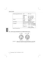
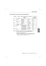
Страница 7: ...z 5 h 100 300 2 50 grün 10 h 7571 5 3P N 50 60 120 208 144 250 blau 9 h 200 346 240 415 rot 6 h 277 480 288 500 schwarz 7 h 347 600 400 690 schwarz 5 h 60 250 440 265 460 1 rot 11 h Tabelle 5 4 Kennfarbe und Anordnung bezogen auf die Unverwechselbarkeitsnut für verschiedene Spannungen und Frequenzen gemäß IEC 60 309 2 1 Hauptsächlich für Schiffsinstallationen 2 Frequenzen 100 Hz führen zu höherem ...

Страница 8: ...ordnung und Montage 6 1 Maßzeichnungen Abbildung 6 1 Maßzeichnung Typ 7571 11 4 und Typ 7571 11 5 Abbildung 6 2 Maßzeichnung Typ 7571 12 506 Ausführungen Abmessungen mm A B 7571 12 4 32 A 3P 57 99 7571 12 5 32 A 3P N 63 4 102 Tabelle 6 1 Verschiedene Ausführungen des Steckers Typ 7571 12 ...

Страница 9: ...Sie die Wandsteckdose Typ 7571 11 mit vier Schrauben in senkrechter Gebrauchslage an einer ebenen Wand Befestigungsmaße siehe Maßskizze bzw Geräterückseite Die Befestigungsbohrungen sind als Langlöcher ausgebildet Dadurch ist ein vertikaler und horizontaler Montageausgleich möglich Montage Typ 7571 12 Gebrauchslage Der Stecker sollte im ungesteckten Zustand hängend mit den Kontakt stiften nach unt...

Страница 10: ...sichere Stromkreise Für eigensichere Stromkreise dürfen nur 2 adrige Leitungen ohne Abschirmung ver wendet werden Achten Sie bei der Leitungsverlegung gemäß EN 50 020 auf Isolationsvermögen und Trennabstände zwischen eigensicheren und nicht eigensicheren Stromkreise und de ren entsprechende Kennzeichnung Beachten Sie auch die EN 60079 14 Abschnitt 12 7 1 2 Leitungsanschluss Verwenden Sie zur Einfü...

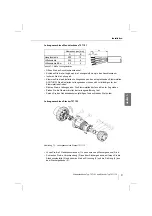
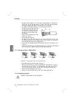
Страница 11: ... die Leitungen aus Die Klemmstellen dürfen nicht unter Zug stehen Ziehen Sie die Überwurfmutter der Leitungseinführung fest Setzen Sie den Gehäusedeckel sorgfältig auf und schrauben Sie Ihn fest Leitungsanschluss Stecker 7571 12 Abbildung 7 1 Leitungsanschluss Stecker 7571 12 Lösen Sie die 3 Gehäuseschrauben 1 und nehmen das Steckergehäuse 2 ab Schrauben Sie die Verschraubung 3 aus dem Steckergehä...

Страница 12: ...ckring 5 Dichtung 6 und das Steckergehäuse 2 Passen Sie die Innendurchmesser der Dichtung 6 gegebenenfalls durch ausschneiden an die Leitung an Schwenken Sie die Zugentlastung 7 am Steckerkragen um 90 ab Isolieren Sie die Leitung ab und klem men Sie diese am Steckerkragen an Die abisolierten Leitungsenden müs sen ganz in die Klemmhülse einge führt werden Ziehen Sie die Schrauben der Klemm hülsen m...

Страница 13: ...icht benutzte Bohrungen mit gemäß Richtlinie 94 9 EG bescheinigten Verschlussstopfen abgedichtet sind Typ 7571 11 Die Wandsteckdose Typ 7571 11 ist nur bei eingestecktem Stecker einschaltbar Es dürfen nur Stecker vom Typ 7571 12 8571 12 7578 12 und 8578 12 der Fa R STAHL verwendet werden Achten Sie bei gezogenem Stecker darauf dass der Klappdeckel der Steckdose mit dem Bajonettring verschlossen is...

Страница 14: ...Rahmen der Wartung die Leitung auf festen Sitz die Einhaltung der zulässigen Temperaturen nach EN 50 014 das Kunststoffgehäuse auf Rissbildung die Buchsen auf Verschmutzung die Dichtungen auf Beschädigungen die bestimmungsgemäße Funktion die Oberfläche der Steckerstifte darf nicht beschädigt sein Nach jedem im Hauptstromkreis des Schalters aufgetretenen Kurzschluss muss der kom plette Steckdosenfl...

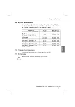
Страница 15: ...r in Originalverpackung gestattet 11 Entsorgung Beachten Sie die nationalen Abfallbeseitigungsvorschriften Benennung für Typ Bestellnummer Verschlussstopfen Typ 8290 3 M32 M 32 x 1 5 7571 11 82 900 37 59 0 Kabel und Leitungseinführung Typ 8161 5 M32 21 M 32 x 1 5 7571 11 61 610 79 01 0 Schutzkappe 7571 12 4 85 710 01 14 0 Schutzkappe 7571 12 5 85 710 02 14 0 Montagesatz Hilfskontakte Oe 7571 11 85...

Страница 16: ...Entsorgung 14 Wandsteckdose Typ 7571 11 und Stecker Typ 7571 12 deutsch ...

Страница 17: ... and information in these operating instructions Characteristic values and rated operating conditions on the rating and data plates Additional instruction plates labels on the device that any damage can invalidate the Ex protection that the power supply has been disconnected before opening the device that the socket s hinged cover is closed with the bayonet ring when the plug is pulled out that su...

Страница 18: ...tected electrical apparatus They are used to connect moveable and stationary electrical equi pment and to connect cables or circuits in hazardous areas 5 Technical data Please consult the manufacturer if operating conditions are non standard 5 1 Explosion protection data Explosion protection Device group and category II 3 G und D Test certificate as per PTB PTB 05 ATEX 1012 Marking according to Di...

Страница 19: ...torques Terminals Terminal chamber cover of wall mount socket Plug housing max 1 6 Nm max 1 8 Nm max 1 0 Nm Line entries 8571 11 Standard Optional Below 1 x M 32 x 1 5 and 1 x stopping plug M 32 x 1 5 Above max 2 x M 32 x 1 5 Stopping plugs can also be used Metallic cable entries Clamping area Lead diameter Type 7571 11 Type 7571 12 13 21 mm 15 28 mm Auxiliary contacts optional ON OFF trailing lea...

Страница 20: ...ing capacity as per IEC 60 947 AC3 Auxiliary contacts AC15 AC15 AC12 DC13 690 V 32 A 500 V max 1250 VA 230 V max 1380 VA 500 V max 3000 VA 110 V max 110 W Power 7 5 kW 15 kW 30 kW 220 230 240 V 380 400 415 V 600 690 V Back up fuse max 35 A gL w o thermal protection max 63 A gL with thermal protection Type of connection Type 7571 11 Type 7571 12 Auxiliary contacts 2 x 2 5 10 mm single wire 2 x 2 5 ...

Страница 21: ...100 300 2 50 green 10 o clock 7571 5 3P N 50 60 120 208 144 250 blue 9 o clock 200 346 240 415 red 6 o clock 277 480 288 500 black 7 o clock 347 600 400 690 black 5 o clock 60 250 440 265 460 1 red 11 o clock Table 5 4 Colour coding and configuration are assigned as per IEC 60 309 2 pin and sleeve standard that makes the mating of plugs and receptacles of different voltages and frequencies impossi...

Страница 22: ...6 Arrangement and fitting 6 1 Dimension drawings Figure 6 1 Dimension drawing for Type 7571 11 4 and Type 7571 11 5 Figure 6 2 Dimension drawing for Type 7571 12 506 Versions Dimensions mm A B 7571 12 4 32 A 3P 57 99 7571 12 5 32 A 3P N 63 4 102 Table 6 1 Various versions of plug Type 7571 12 ...

Страница 23: ...ounting socket Type 7571 11 with four screws to the application position on an evenly surfaced wall for mounting dimensions see the dimension sketch or the reverse side of device The mounting holes are oblongly shaped slots These holes facilitate correct vertical and horizontal mounting Installation of Type 7571 12 Application position In the unplugged state the plug should be stored hanging with ...

Страница 24: ...Intrinsically safe circuits Only 2 wire leads without shielding may be used for intrinsically safe circuits When laying cable as per EN 50 020 pay attention to insulation properties and isolation distances between intrinsically safe and non intrinsically safe circuits in the according labelling Also adhere to EN 60079 14 Section 12 7 1 2 Lead connection When routing in and connecting cable and lea...

Страница 25: ...ing plate Correctly orient the leads The terminal clamps must not be subjected to tension pulling forces Tighten the cap nut of the cable entry Carefully replace the enclosure cover and screw it in place Lead connection for plug 7571 12 Figure 7 1 Lead connection for plug 7571 12 Loosen the 3 enclosure screws 1 and remove the plug enclosure 2 Unscrew the gland nut 3 from the plug enclosure Remove ...

Страница 26: ...ring 5 gasket 6 and the plug enclosure 2 If necessary adjust the inner diameter of the gasket 6 by cutting it to accommodate the lead diameter Swing back 90 the strain relief 7 so that it is positioned near the plug collar Strip the lead and clamp it in the plug collar The stripped lead ends must be completely introduced into the clam ping sleeve Tighten the screws of the clamping sleeve using 1 2...

Страница 27: ...d drilled holes are sealed with stoppers certified as compliant with Directive 94 9 EC Type 7571 11 Wall mounting socket Type 7571 11 is only supplied with power when a plug is inserted It should only be used in conjunction with Type 7571 12 8571 12 7578 12 or 8578 12 plugs from R STAHL Make sure that the socket s hinged cover is closed with the bayonet ring when the plug is pulled out Type 7571 1...

Страница 28: ...ecked during maintenance that the cable is securely seated the maximum permissible temperatures according to EN 50 014 are adhered to the plastic enclosure shows no signs of crack formation the socket sleeves are free of dirt the gaskets and seals are checked for damage the function is in accordance with regulations the surface of the plug pins must not be damaged Subsequent to each short circuit ...

Страница 29: ...ckaging 11 Disposal Please observe the national waste disposal regulations Designation for Type Ordering code Stopping plug Type 8290 3 M32 M 32 x 1 5 7571 11 82 900 37 59 0 Cable and line entries Type 8161 5 M32 21 M 32 x 1 5 7571 11 61 610 79 01 0 Protective cap 7571 12 4 85 710 01 14 0 Protective cap 7571 12 5 85 710 02 14 0 Auxiliary contacts installation set Oe 7571 11 85 708 01 76 0 Auxiliar...

Страница 30: ...Disposal 28 Wall mounting socket Type 7571 11 and plug Type 7571 12 english ...

Страница 31: ... 079 14 les règles de l art dans le domaine technique les consignes de sécurité et données du présent mode d emploi les caractéristiques techniques et les conditions d utilisation indiquées sur les plaques signalétiques les indications complémentaires sur l appareil que toute détérioration du matériel peut avoir pour conséquence de rendre inopérante la protection antidéflagrante couper l alimentat...

Страница 32: ...type 7571 12 sont des matériels antidéflagrants Elles servent à raccorder des appareils électriques fixes et mobiles ainsi qu à la con nexion de câbles ou circuits dans des zones explosibles 5 Caractéristiques techniques En cas de conditions d utilisation différentes veuillez contacter le constructeur 5 1 Caractéristiques antidéflagrantes 5 2 Données mécaniques Protection antidéflagrante Groupe d ...

Страница 33: ... câbles 8571 11 Version standard En option en bas 1 x M 32 x 1 5 et 1 x bouchon M 32 x 1 5 en haut 2 x M 32 x 1 5 maxi bouchon aussi en option Entrées métalliques Plage de serrage Diamètre de câbles Type 7571 11 Type 7571 12 13 21 mm 15 28 mm Contacts auxiliaires en option MARCHE ARRÊT retardé avancé Tableau 5 2 Données mécaniques Tension d utilisation assignée Contacts auxiliaires 690 V CA maxi 5...

Страница 34: ...s prises à collet sur les douilles de contact Puissance 7 5 kW 15 kW 30 kW 220 230 240 V 380 400 415 V 600 690 V Fusible de puissance puissance de base 35 A maxi sans protection thermique puissance de base 63 A maxi avec protection thermique Type de raccordement Type 7571 11 Type 7571 12 Contacts auxiliaires 2 x 2 5 10 mm monobrin 2 x 2 5 6 mm à brins fins 1 x 2 5 10 mm à brins fins 2 x 0 5 2 5 mm...

Страница 35: ...0 noir 5 h 100 300 2 50 vert 10 h 7571 5 3P N 50 60 120 208 144 250 bleu 9 h 200 346 240 415 rouge 6 h 277 480 288 500 noir 7 h 347 600 400 690 noir 5 h 60 250 440 265 460 1 rouge 11 h Tableau 5 4 Couleur d identification et disposition correspondant à la rainure de détrompage relative à différentes tensions et fréquences selon CEI 60 309 2 1 Principalement pour installations sur navires 2 Les fré...

Страница 36: ...sposition et montage 6 1 Plans d encombremen Figure 6 1 Plan d encombrement type 7571 11 4 et type 7571 11 5 Figure 6 2 Plan d encombrement type 7571 12 506 Versions Dimensions mm A B 7571 12 4 32 A 3P 57 99 7571 12 5 32 A 3P N 63 4 102 Tableau 6 1 Différentes versions de la fiche type 7571 12 ...

Страница 37: ... le haut Fixez la prise à bride type 7571 11 à l aide de quatre vis en position d utilisation verti cale sur une paroi plane Pour les cotes de fixation voir le plan d encombrement ou la face arrière de l appareil Les perçages de fixation sont des trous oblongs Un ajustage du montage est ainsi possible Montage type 7571 12 Position d utilisation La fiche doit être conservée débranchée pendant avec ...

Страница 38: ...lindage Lors de la pose du conducteur assurez vous que le pouvoir isolant et les distances de séparation entre les circuits électriques avec protection intrinsèque et sans protection intrinsèque ainsi que les repérages correspondants soient conformes à la norme EN 50 020 Observez aussi la norme EN 60079 14 paragraphe 12 7 1 2 Raccordement des conducteurs Pour l entrée des câbles et des conducteurs...

Страница 39: ...conducteurs Les points de serrage ne doivent pas être sous contrainte Serrez à fond la collerette de fixation de l entrée de conducteur Placez avec précaution le couvercle de boîtier et vissez le à fond Raccordement de conducteur fiche 7571 12 Figure 7 1 Raccordement de conducteur fiche 7571 12 Desserrez les 3 vis du boîtier 1 et enlevez le boîtier de la fiche 2 Retirez le raccord à vis 3 du boîti...

Страница 40: ...boîtier de la fiche 2 Adaptez le diamètre inté rieur du joint d étanchéité 6 au conducteur par découpe si besoin Pivotez le délestage de traction 7 au niveau de la collerette de la fiche de 90 Dénudez le conducteur et coincez le sur la collerette de la fiche Les extré mités de conducteur dénudées doi vent être complètement introduites dans les douilles de serrage Serrez les vis des douilles de ser...

Страница 41: ...fiés conformes à la directive 94 9 CE et les alésages sans utilisation sont étanchés avec des bouchons certifiés conformes à la directive 94 9 CE Type 7571 11 La prise murale type 7571 11 ne peut être enclenchée que si la fiche est insérée On ne doit utiliser que les fiches type 7571 12 8571 12 7578 12 et 8578 12 de la société R STAHL Assurez vous qu en cas de fiche retirée le couvercle rabattant ...

Страница 42: ...lors de l entretien si le conducteur est bien fixé le respect des températures admissibles selon EN 50 014 si le boîtier en polyester présente des formations de fissures si les douilles sont encrassées si les joints sont endommagés l appareil est utilisé conformément à sa fonction la surface des pointes de contact n est pas endommagée Après chaque court circuit se produisant dans le circuit princi...

Страница 43: ...origine 11 Réglementation concernant les déchets Respecter les réglementations nationales en matière d élimination des déchets Désignation pour type Référence Bouchon type 8290 3 M32 M 32 x 1 5 7571 11 82 900 37 59 0 Entrée de câbles et de conducteurs Typ 8161 5 M32 21 M 32 x 1 5 7571 11 61 610 79 01 0 Capuchon 7571 12 4 85 710 01 14 0 Capuchon 7571 12 5 85 710 02 14 0 Kit de montage contacts auxi...

Страница 44: ...Réglementation concernant les déchets 42 Prise murale type 7571 11 et connecteur type 7571 12 français ...

Страница 45: ...Anhang Appendix Annexes Typen Types 8571 11 8571 12 A 1 ...

Страница 46: ......

Страница 47: ...olicitar de su representante R STAHL estas instrucciones de servicio en otro idioma de la Union Europea Se desiderate la traduzione del manuale operativo in un altra lingua della Comunit à Europea po tete richiederla al vostro rappresentante R STAHL Indien noodzakelijk kan de vertaling van deze gebruiksinstructie in een andere EU taal worden opgevraagd bij uw R STAHL vertegenwoordiging Har ni beho...

Страница 48: ...75 716 01 30 0 S BA 7571 00 de en fr 04 2005 R STAHL Schaltgeräte GmbH Am Bahnhof 30 74638 Waldenburg Württ www stahl de ...

Отзывы: