UM1925
Hardware description
and configuration
DocID028121 Rev 1
7/17
Mode
Max output
current
Output
R
DS(on)
OCD
threshold
scaling
J1
J2
J3
J4
Parallel all bridges
one unidirectional DC
motor
11.2 A rms
0.075 Ω
× 4
Connected
Connected
Connected
Connected
Notes:
(1)
The current limit is shared between the two motors connected on the same full-bridge (A or B).
2.2.1
Mode no. 1: two bidirectional DC motors
Two independent DC motors are driven by the board.
The supply voltage of both motors is connected to J1 pin 5 and 6 with a maximum voltage
at 50 V DC.
Maximum current is 2.8 A rms and the output R
DS(on)
is equal to 0.3 W (T
J
= 25 °C).
The maximum overcurrent detection threshold is set to 5.6 A.
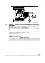
Motor A connected between A+ (CN1 pin1) and A- (CN1 pin2)
Motor B connected between B+ (CN1 pin4) and B- (CN1 pin3)
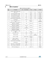
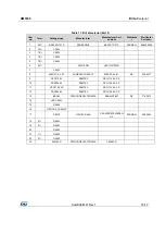
Table 4: Jumper selection
J1
J2
J3
J4
Disconnected
Disconnected
Disconnected
Disconnected
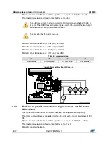
Figure 4: two bidirectional DC motors
2.2.2
Mode no. 2: four DC motors unidirectional
Four independent DC motors are driven by the board.
The supply voltage of both motors is connected to J1 pin 5 and 6 with a maximum voltage
of 50 V DC.


