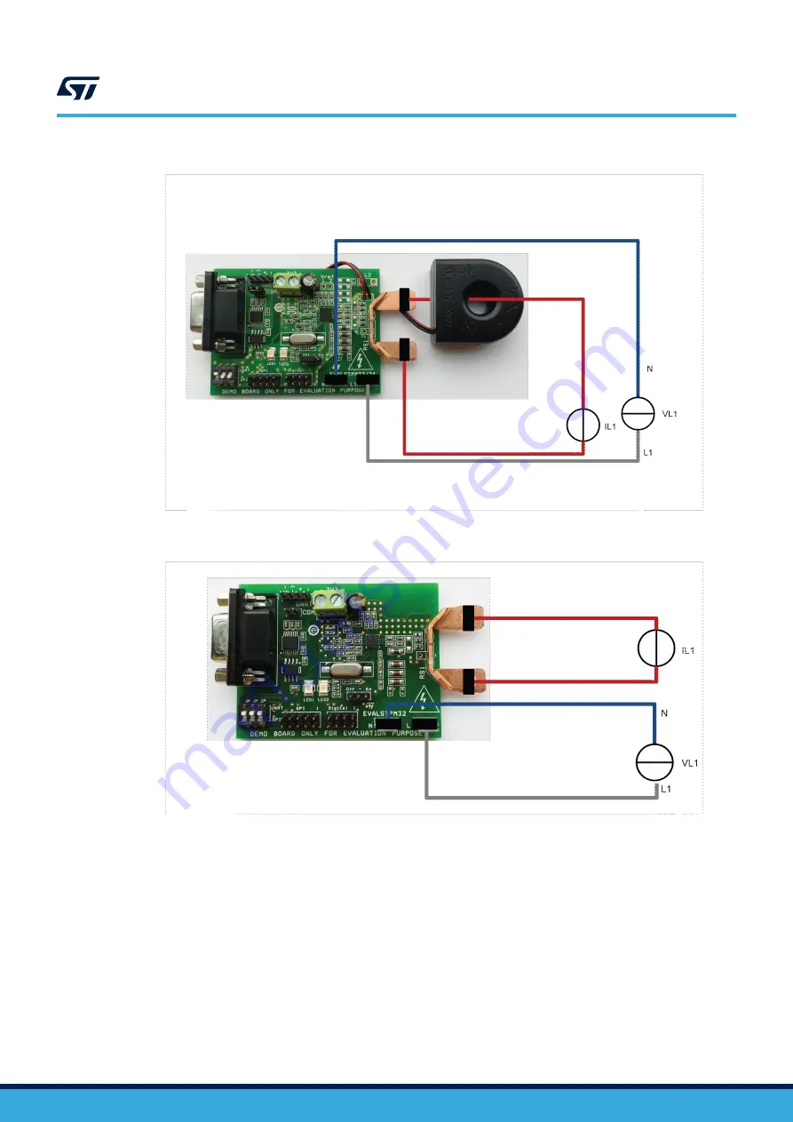
Figure 5.
Board connection to phantom load, single-phase system with neutral monitoring (STPM34 and
STPM33)
Figure 6.
Board connection to phantom load, single-phase system (STPM3x)
UM1748
Connection to the line
-
Rev 3
page 8/15
Страница 1: ...12 2x for AC watt meters All calculated data as well as configuration parameters are stored in internal 32 bit registers accessible through SPI or UART peripheral Three boards are available for evalua...
Страница 2: ...1 Overview Figure 1 EVALSTPM34 board Figure 2 EVALSTPM33 board UM1748 Overview UM1748 Rev 3 page 2 15...
Страница 3: ...5 ARMS Imax maximum current 100 ARMS CP constant pulses 41600 imp kWh fline line frequency 50 60 Hz 10 TOP operating temperature 40 85 C 1 3 Recommended readings This document describes how to use and...
Страница 4: ...e L2 2 Secondary voltage I1 Primary current I2 Secondary current 1 For the EVALSTPM34 and the EVALSTPM33 board only 2 For the EVALSTPM34 board only 2 1 2 Power supply The board does not contain a powe...
Страница 5: ...ng the STEVAL IPE023V1 isolated USB dongle the STPM3x SPI peripheral has to be selected All SW1 switches have to be in OFF position before the device powers up SPI pins are available in J6 connector f...
Страница 6: ...e EVALSTPM34 board has two currents and two voltage channels while the EVALSTPM33 has two currents and one voltage channel and the EVALSTPM32 has one current and one voltage channel available Main des...
Страница 7: ...e connected to line voltage and current in several ways as shown in below pictures Please note that in boards using shunt the shunt is at the same potential of voltage neutral Faston and therefore it...
Страница 8: ...d connection to phantom load single phase system with neutral monitoring STPM34 and STPM33 Figure 6 Board connection to phantom load single phase system STPM3x UM1748 Connection to the line UM1748 Rev...
Страница 9: ...to isolated AC source STPM34 and STPM33 Figure 8 Board connection to mains 2 3 Board setup Regarding to the STPM3x evaluation software setup and use please refer to user manual UM1719 UM1748 Board set...
Страница 10: ...in Section 2 2 Connection to the line without powering it on 5 Connect the USB cable both to the board and to PC 6 Power on AC source and DC source 7 Open GUI 8 Click options then interface select US...
Страница 11: ...he device basic configuration section Removed the schematic section Changed figure titled Board connection to phantom load single phase system STPM3x and figure titled Board connection to isolated AC...
Страница 12: ...1 4 Digital output 5 2 1 5 SPI connection 5 2 1 6 On board USB UART connection 6 2 1 7 Metrology 6 2 1 8 LED 6 2 1 9 Clock 6 2 1 10 Voltage reference 7 2 2 Connection to the line 7 2 3 Board setup 9 2...
Страница 13: ...ion board setting and configuration terminals 4 Table 3 J5 connector pinout 5 Table 4 J6 SPI connector pinout 5 Table 5 J2 UART connector 6 Table 6 EVALSTPM3x evaluation board parameters 6 Table 7 Doc...
Страница 14: ...ase system STPM34 7 Figure 5 Board connection to phantom load single phase system with neutral monitoring STPM34 and STPM33 8 Figure 6 Board connection to phantom load single phase system STPM3x 8 Fig...
Страница 15: ...s and ST assumes no liability for application assistance or the design of purchasers products No license express or implied to any intellectual property right is granted by ST herein Resale of ST prod...