Channel#4. INFRARED DETECTOR
30
6. CHANNEL#4. INFRARED DETECTOR
The channel is designed to detect eavesdropping devices transmitting information in the
IR-range. The detector sensor is located on the top panel of the main unit
The analysis of the detected signals is carried out using:
graphic information (oscillogram and received signal level indicator);
acoustic information (headphones or built-in speaker).
Switching on is carried out from the MAIN MENU
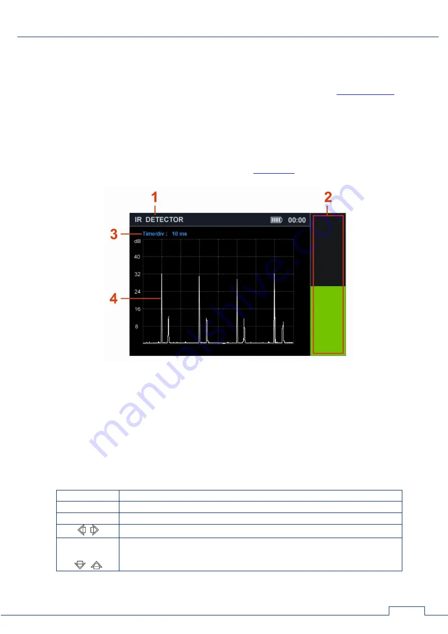
The device screen after switching on the channel is shown in Fig.26.
Fig.26
In Fig.26:
1 - INFRARED DETECTOR is on
2 - Received signal level indicator
3 - Division value of the time axis (horizontal axis)
4 - Oscillogram
Controls:
Button
Action
ESC, MODE
Switch to MAIN MENU
ENTER
Turn on/off DIFFERENTIAL mode
Scaling oscillogram along the horizontal axis
F1 - F4
FUNC
Not used


