SST 5136-DNP-PCI Скачать руководство пользователя страница 22

5136-DNP-PCI

Hardware Reference

© 1999 SST/Woodhead Canada Limited

18

Appendix B 

Card Error Messages

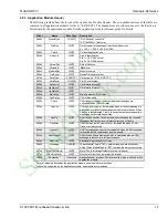
These errors may be reported by the card either during its startup self-test or if a run-time fatal error is
encountered. An error message reported by the card is placed in the message area (0040h) of the host interface and
can be displayed using the status applications provided with the interface card.

Error 1: RAM data test failed

An error occurred during testing of the RAM data bus. The card should be returned for repair.

Error 2: RAM address test failed

An error occurred during testing of the RAM address bus. The card should be returned for repair.

Error 3: RAM A16 address test failed

An error occurred during testing of the RAM A16 signal. The card should be returned for repair.

Error 4: RAM A17 address test failed

An error occurred during testing of the RAM A17 signal. The card should be returned for repair.

Error 5: Module checksum is invalid

The application module is invalid. Each application module has a checksum to verify file integrity. 
Since the checksum is validated by the loader, the most likely cause of this error is an undetected 
memory failure.

If this error occurs with more than one application module, the card should be returned for repair.

Error 6: CAN reset flag failed to clear

An error occurred testing the CAN controller. The card should be returned for repair.

Error 7: CAN data test failed

An error occurred testing the CAN controller data bus. The card should be returned for repair.

Error 8: CAN address test failed

An error occurred testing the CAN controller address bus. The card should be returned for repair.

Error 9: Invalid NVRAM data

The non-volatile memory on the card contains invalid information. The card should be returned for 
repair.

Error 10: Execution permission denied

This card has not been configured to execute the application module. Contact the vendor of the 
application module for assistance. See the Software Reference Guide for information on application 
security.

Error 11: Application initialization error

An error occurred initializing the application module. Report this condition to the vendor of the 
application module.

Error 12: Unknown application initialization code

An error occurred initializing the application module. Report this condition to the vendor of the 
application module.

Error 13: Application terminated

The application module terminated (abnormal condition). Run the status utility provided and record 
the results. Report this condition to the vendor of the application module.

Be sure to record the Main and Additional error codes as these will identify the exact source of the error.

StockCheck.com

Содержание 5136-DNP-PCI

Страница 1: ...DNP PCI Hardware Reference Version 1 0 50 Northland Road Waterloo Ontario N2V 1N3 519 725 5136 fax 519 725 1515 1999 SST a division of Woodhead Canada Limited Printed in Canada S t o c k C h e c k c...

Страница 2: ...Canada Limited i Publication Name Publication Revision Date Printed DNP PCI doc 1 0 7 21 99 1999 SST Woodhead Canada Limited SST is a trademark of Woodhead industries Inc This Document Applies To 5136...

Страница 3: ...Termination Resistor 4 3 4 Connecting to a CAN Network 5 3 4 1 Termination Resistor 5 3 4 2 Power 5 3 5 Grounding 5 4 Hardware Technical Information 6 4 1 Introduction 6 4 2 DeviceNet Pro Mode Registe...

Страница 4: ...ions 13 4 5 2 Byte Ordering 13 4 5 3 Application Module Header 14 4 6 Loading an Application Module in Compatible Mode 15 4 6 1 Test for 5136 DNP PCI at I O port address specified 15 4 6 2 Check for c...

Страница 5: ...terface card for communication with DeviceNet and other CAN based networks The main features of the 5136 DNP PCI are 33 MHz 32 bit PCI interface fully compliant with PCI 2 1 Spec 40 MHz AM186EM microp...

Страница 6: ...plug in to any 5V PCI motherboard connector The 5136 DNP PCI does not require that the motherboard connector supply 3 3V power The 5136 DNP PCI will not plug in to 3 3V only PCI connectors 2 2 2 CAN...

Страница 7: ...PCI card Color Status Off No Power Green Application module loaded and running Red Application module not loaded an error occurred during the load or a runtime fatal error occurred 2 3 2 Health Indica...

Страница 8: ...touching only the edges of the card Do not touch the header pins or the surface of the board 6 Firmly press the 5136 DNP PCI card into the PCI connector 7 Secure the card to the case using the screws...

Страница 9: ...adjacent terminal 3 4 1 Termination Resistor The 5136 DNP PCI does not have a built in termination resistor You must add termination in accordance with the requirements of the target CAN network 3 4 2...

Страница 10: ...qPending CardInt Bit Name Description Card Int CINT This bit is used to send interrupts to the card processor Writing 1 generates an interrupt to the card Writing 0 has no effect Reading 1 indicates i...

Страница 11: ...tes whether or not the card will boot from the on board Flash memory When this bit is 1 the card is set to boot from Flash RAM When this bit is 0 the card is set to boot from Static RAM WDT This bit i...

Страница 12: ...e linearly accessed in the 256K window Bank 0 being mapped to the lowest 16K through to Bank 15 mapped to the highest 16K See section 4 2 5 Reserved These bits are reserved for future expansion Always...

Страница 13: ...1 0 Read Write R R R R R R R R Reset 0 Name Reserved Bit Name Description Reserved These bits are reserved for 32 bit and 24 bit address selection 4 2 8 Memory Configuration Register 3 MCR3 Memory Add...

Страница 14: ...his bit is a semaphore between the card processor and the host It determines who has control of the EEPROM Writing 1 indicates that the host would like control Writing 0 indicates that the host no lon...

Страница 15: ...ther or not the card s shared memory will respond to host memory accesses This may be used to multiplex several 5136 DNP cards at the same base address by enabling the memory on one card at a time Wri...

Страница 16: ...dentification Register IDR Base Address 7 IDR at Base Address 7 is identical to that of ProMode Refer to section 4 2 10 4 4 PCI Configuration Upon power up the PCI Configuration is as follows PCI CFG...

Страница 17: ...irst 128 bytes of the host interface block for loader interface and run time status information common to all 5136 DNP PCI applications This area is called the Application Module Header 4 5 1 Data Typ...

Страница 18: ...r Incremented when messages are submitted to the CAN controller 0034h CanAck UINT2 CAN ack error counter Incremented when a transmit message is aborted due to lack of acknowledgment from other station...

Страница 19: ...ents of the target address and abort the load procedure 5 Refer to section 4 6 10 for further instructions 6 Repeat steps 1 3 for the entire target memory block 4 6 3 Enable and test the card RAM 1 Wr...

Страница 20: ...dule Header does not contain DN or ER the application module failed to start 2 Refer to section 4 6 10 for further instructions 3 If ModuleType contains ER the card diagnostic has detected an error 4...

Страница 21: ...densing Network Cable Shielded twisted pair compatible with target network External Power 11 24 VDC 50mA Isolation 500V Protocol CAN 2 0 A B Data Rate Up to 1 Mbaud PCI Bus Spec PCI Spec 2 1 compliant...

Страница 22: ...uld be returned for repair Error 6 CAN reset flag failed to clear An error occurred testing the CAN controller The card should be returned for repair Error 7 CAN data test failed An error occurred tes...

Страница 23: ...used this error Error 24 Invalid CAN interrupt This error should be reported to the vendor of the application module Make note of the circumstances that caused this error Error 25 Nested system timer...

Страница 24: ...led Operating system type and version Details of the problem you are experiencing application module type and version target network circumstances that caused the problem Getting Help Technical suppor...

Страница 25: ...rned to it freight prepaid which prove upon examination to be within the Warranty definitions and time period The Warranty does not cover costs of installation removal or damage to user s property or...

Отзывы: