


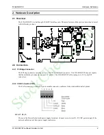


5136-DNP-PCI
Hardware Reference
© 1999 SST/Woodhead Canada Limited
6
4. Hardware Technical Information
4.1 Introduction
This section provides technical hardware information. The information in this section is intended for programmers
familiar with hardware-level PC programming.
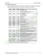
4.2 DeviceNet Pro Mode Register Interface
Offset
Register
7
6
5
4
3
2
1
0
0
CCM
Reserved
MemEn
IrqPending
CardInt
1
SP1
Reserved
2
CCR
CardRun
WDT
FlashEn
Mode
Reserved
MCRSel
3
MCR0
Reserved
Bank
3
MCR1
AddrMode
Win32K
Reserved
3
MCR2
Reserved
3
MCR3
A19
Reserved
4
ICR
Reserved
IrqMode
Reserved
5
SP2
Reserved
6
SP3
Reserved
7
AIDR
IdMode
Lock
Reserved
SEL
Di
Do
CLK
7
SIDR
IdMode
CardId
4.2.1 Card Command Register - CCM - Base A 0
Bit
7
6
5
4
3
2
1
0
Read/Write
R
R
R
R
R/W
R/W
R/W
R/W
Reset
0
0
0
0
Name
Reserved
MemEn
IrqPending
CardInt
Bit Name
Description
Card Int
(CINT)
This bit is used to send interrupts to the card processor.
•
Writing 1 generates an interrupt to the card
•
Writing 0 has no effect
•
Reading 1 indicates interrupt in progress.
•
Reading 0 indicates interrupt complete.
IrqPending
This bit indicates that an interrupt from the card is still pending.
•
Writing 1 acknowledges the interrupt (and clears this condition)
•
Writing 0 has no effect
•
Reading 1 indicates interrupt in progress.
•
Reading 0 indicates interrupt complete.
MemEn
These bits indicate and control whether or not the card’s shared memory will
respond to host memory accesses. This may be used to multiplex several
5136-DNP-PCI cards at the same base address by enabling the memory on one
card at a time.
•
Writing 01 Disables card memory
•
Writing 10 Enables card memory
•
Writing 11 or 00 has no effect
•
Reading 11 indicates that this card’s memory is currently enabled.
•
Reading 00 indicates that this card’s memory is currently disabled.
StockCheck.com