


Form No. 1000542
Rev. 2 November 14, 2014
© SPX
Operating Instructions for:
PE39PED1BPR
PE39PED1PR
PE39YED1BPR
PE39YED1PR
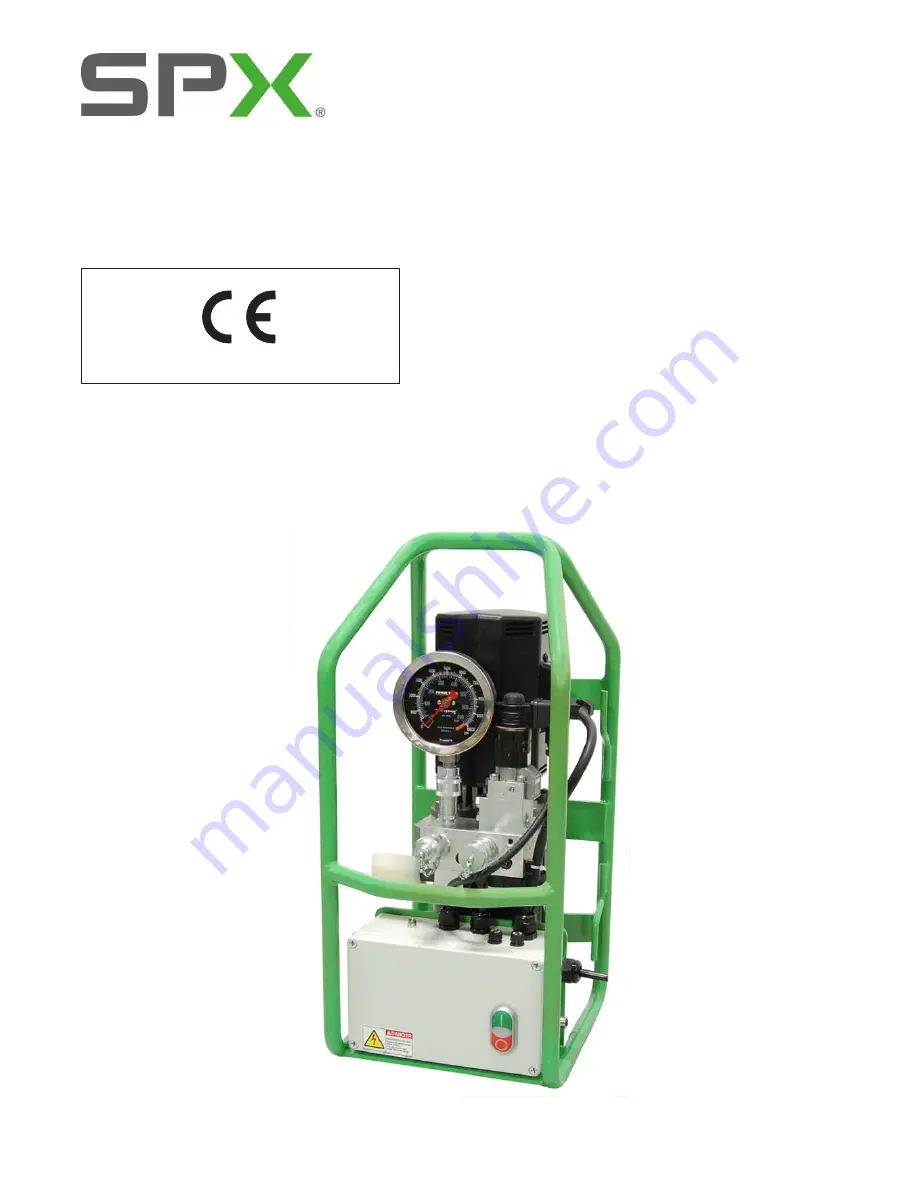
PE39 Series
Compact Torque Wrench Pump
SPX Bolting Systems
Unit 4, Wansbeck Business Park
Rotary Parkway
Ashington
Northumberland NE63 8QW
spxboltingsystems.com
Tel: +44 (0) 1670 850580
Fax: +44 (0) 1670 850655
Original Instructions