background image

Matrix 908 Field Computer

28

www.teejet.com

NO.3 CREATE AN APPLICATION BOUNDARY

Application boundaries establish the work areas where product is or is not applied while using Automatic Section Control (ASC) or BoomPilot.

Application is not required to map a boundary.

If mapping a boundary with one or more sections folded in and turned off, it is necessary to maintain this section configuration for the duration 

of the boundary pass. Any changes made to the number of sections turned on, and therefore the width of the machine after the boundary 
mapping process has started, will result in the application mapping the boundary at the outer edge of all the programmed sections – not 
necessarily those turned on at any given time during the boundary pass.

When mapping a boundary with some sections turned off, it is necessary to turn BoomPilot to Manual mode and turn ON the master and 
section switches for all sections that will be used during the boundary pass. Once the boundary pass is complete the sections switches can 
be turned OFF, master switch remains ON, BoomPilot can be returned to Automatic  
mode and automatic section control can then be used.

NOTE:  If a boundary is mapped with some sections folded as described above, it may be necessary to use the ADJUST GUIDELINE icon 

 on the guideline over to the correct position for subsequent passes in the field.

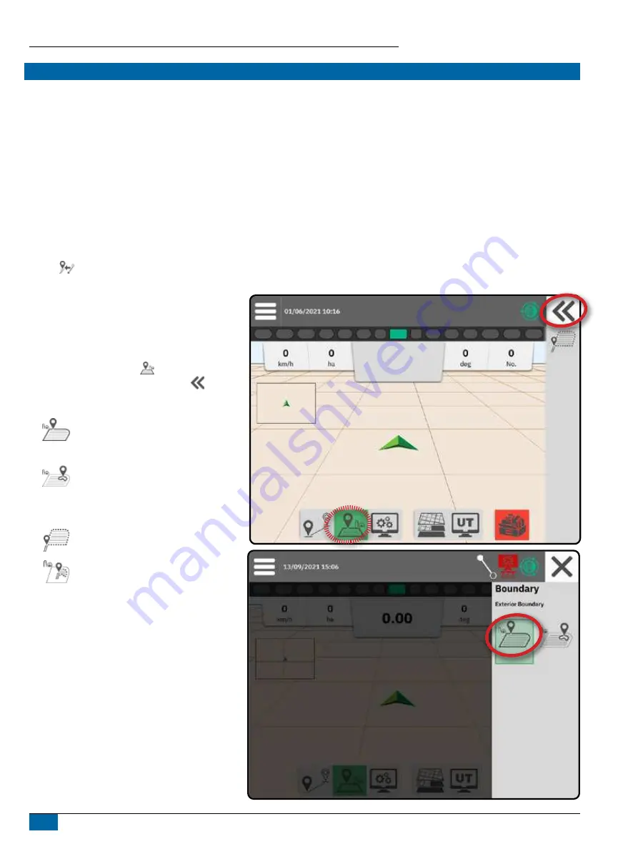
Establishing an Exterior or Interior 
Boundary

1. Drive to a desired location at the perimeter of 

the application area and orientate the vehicle in 
association to the established mapping location.

2. With the Boundary button 

 on the Feature Bar 

active, press the Slide-Out Tray button 

.

3. Select the type of boundary to be mapped.

 Exterior Boundary – establishes a work 

area where application will be applied 
while using ASC or BoomPilot.

 Interior Boundary – establishes a work 

area where application will NOT be applied 
while using ASC or BoomPilot.

4. Press MARK BOUNDARY icon

Start Exterior Boundary 

Start Interior Boundary 

5. Acknowledge that the default mapping location will 

be used.

Содержание TeeJet Matrix 908

Страница 1: ...98 01578 R0 U S E R G U I D E...

Страница 2: ...elete a Device 14 Assisted Auto Steering Device 15 NO 4 SET UP GUIDANCE AND MAPPING 16 Mapping Location 16 NO 5 SET UP THE GNSS 17 NO 6 SELECT JOB MODE 18 Job Manager 19 START A JOB 20 Simple Job Mode...

Страница 3: ...t and improve efficiency while working in the field The driver has full responsibility for the quality and work related results Disengage or remove any assisted auto steering device before operating o...

Страница 4: ...lier The operator should have full information on the nature and the quantity of the material to be distributed ADHERE TO FEDERAL STATE AND LOCAL REGULATIONS REGARDING THE HANDLING USE OR DISPOSAL OF...

Страница 5: ...and hoses from implement and machine operational zones When cleaning equipment protect harness cables from high pressure wash NOTE TOUCH SCREEN CARE Keep sharp objects away from the touch screen devi...

Страница 6: ...the Vehicle Pivot Point to the Hitch Point Lateral Distance from the Vehicle Centreline to the Hitch Point In Line Distance from the Vehicle Pivot Point to the Antenna Lateral Distance from the Vehicl...

Страница 7: ...d Mapping Distances Description Measurement Guidance Width Description Measurement Mapping Location In Line Distance from the Vehicle Pivot Point to the Mapping Location Mapping Location Lateral Dista...

Страница 8: ...and briefly hold the POWER button WARNING Wait 30 seconds before restarting the console Serial Number Take note of your serial number It is required for product registration Product Registration Inte...

Страница 9: ...refer to software release notes for software system connectivity at www teejet com support software aspx Matrix 908 Harness Ethernet Interface Terminator to ISOBUS ECU IC35 Sprayer IC38 Spreader Dyna...

Страница 10: ...rent language switch console units and change the local time zone Press OK to advance to the Vehicle Wizard SETUP THE CONSOLE NO 1 WELCOME SCREEN To Access the Cultural Settings After Initial Startup...

Страница 11: ...d Use to save and close the wizard 2 When finished on the Vehicle Details screen select the BACK ARROW to continue to the Settings Menu To Access the Vehicle Wizard After Initial Startup 1 On the Main...

Страница 12: ...rent selections and close the wizard Next Wizard Option use to go to the next wizard option Finish shown when the end of the wizard options has been reached Use to save and close the wizard Previous S...

Страница 13: ...g 5 Follow the prompts on the Device Wizard NOTE Default values must be acknowledged before advancing to the next wizard option TeeJet CAN Device 1 On the Main Menu on the Settings Menu select Device...

Страница 14: ...ect the device card to be activated 3 On the Device Details screen select the EDIT SETTINGS icon 4 Select the SAVE AND CLOSE button 5 When finished select YES when asked if you would like to make this...

Страница 15: ...ering Device on System Start 3 Restart the console 4 On the Main Menu on the Settings Menu select Assisted Auto Steering 5 Make adjustments to settings as needed Changes are automatically applied 6 To...

Страница 16: ...xterior of the outermost active section While creating an interior boundary the line will be to the interior of the innermost active section If no sections are active the boundary will be marked to th...

Страница 17: ...nu on the Settings Menu select GNSS Receiver 2 Under General Settings make adjustments to settings as needed 3 When available under Advanced Settings make adjustments to settings as needed 4 Exit this...

Страница 18: ...t Job menu on the Guidance screen includes options to create a new job or continue the last job X Advanced Mode more than one job may be available at any time Start Job menu on the Guidance screen inc...

Страница 19: ...elete the Selected Job or Jobs Duplicate the Selected Job use to duplicate boundaries and guidelines from the selected job Information on Selected Job use to see and or add details to the selected job...

Страница 20: ...cle Wizard on page 11 and No 3 Set Up Additional Devices on page 12 for details To change between Simple Job mode and Advanced Job mode go to Main Menu Settings Console Job Mode See No 6 Select Job Mo...

Страница 21: ...ager Main Menu Button access to the Settings including wizards Help options and Universal Terminal UT Edit Information select to enter a name using the on screen keyboard Cancel use to exit the Job In...

Страница 22: ...be highlighted Guidance Mode select to access guidance options including selecting a guidance mode and creating deleting and switching guidelines Boundary Mode select to access boundary options Displ...

Страница 23: ...0 NO 1 CHOOSE A GUIDANCE MODE 1 With the Guidance button on the Feature Bar active press the Slide Out Tray button 2 Selects a guidance mode No Guidance Straight AB Guidance Dynamic Adaptive AB Guidan...

Страница 24: ...B guidance provides guidance along a curved line based on an initial AB reference line where each adjacent guideline is drawn from the projected guidance width and heading Circle Pivot Guidance Circle...

Страница 25: ...uidance Action Bar Options Mark A Point use to mark the first point on the guideline Mark B Point use to mark the last point on the guideline and establish the AB line NOTE The MARK B Icon is not avai...

Страница 26: ...c detour mapping A straight line will be drawn between the pause point and the resume point Resume Detour use to resume dynamic detour mapping A straight line will be drawn between the pause point and...

Страница 27: ...ine If more than one guideline is saved the Switch Guideline option will become available To change to other available guidelines 1 Select the Slide Out Tray button 2 Press SWITCH GUIDELINE icon 3 Sel...

Страница 28: ...at will be used during the boundary pass Once the boundary pass is complete the sections switches can be turned OFF master switch remains ON BoomPilot can be returned to Automatic mode and automatic s...

Страница 29: ...avel to within one swath width of the starting point The boundary will close automatically the white guideline will turn black Manual close press the FINISH BOUNDARY icon to close the boundary with a...

Страница 30: ...real time representation of active boom sections is touch responsive to start and stop application mapping when an Application Mapping device or a BoomPilot system has been activated Sections Empty bo...

Страница 31: ...to displayed available options GNSS Status Green GPS GLONASS or SBAS with or without DGPS Required Yellow GPS only Red no GNSS Orange Glide ClearPath Guidance Mode Straight AB or Azimuth Guidance Dyna...

Страница 32: ...nge the format in which the distance is displayed 1 Press the Navigation Activity box 2 Select the measurement format Selectable Job Information X Speed displays the current speed of travel X Heading...

Страница 33: ...08 Field Computer 33 98 01578 EN R0 ACCESS THE UNIVERSAL TERMINAL The Universal Terminal UT is accessible from either the Guidance Screen or Main Menu TwinView use to display both UT and guidance info...

Страница 34: ...ternal to receive external GNSS data Internal uses position data from the internal GNSS receiver these NMEA data are sent out the RS 232 serial Port A of the harness at the selected GNSS Data Rate Ext...

Страница 35: ...ty Enable if TerraStar services are to be used ADVANCED SETTINGS GNSS Refresh The refresh GNSS position button will reset the ClearPath filter in the OEMStar receiver in cases where the user has had t...

Страница 36: ...Bar 2 Select the GNSS icon 3 View data including W HDOP a measure of satellite geometry strength in the horizontal plane A HDOP value of less than 2 is preferred W Position Quality Indicator the curr...

Страница 37: ...networks may be publicly or privately owned operated and may offer a free signal or require an annual subscription fee By accessing a CORS network via a cellular connection the end user eliminates the...

Страница 38: ...get to the internet and the NTRIP server Positional Drift The constant change in the GNSS position calculation primarily caused by atmospheric and ionospheric changes poor satellite geometry possibly...

Страница 39: ...version as well as the software versions of modules connected to the CAN bus User Guide Provides a QR Code to access this user guide online Product Registration Provides a QR Code to register your con...

Страница 40: ...TURES 8 SETUP THE CONSOLE 10 NO 1 WELCOME SCREEN 10 NO 2 WALK THROUGH THE VEHICLE WIZARD 11 NO 3 SET UP ADDITIONAL DEVICES 12 NO 4 SET UP GUIDANCE AND MAPPING 16 NO 5 SET UP THE GNSS 17 NO 6 SELECT JO...

Отзывы: