VOYAGER
®
570G
U S E R M A N U A L
845 SPRAYER
98-05349 R0
Страница 1: ...VOYAGER 570G U S E R M A N U A L U S E R M A N U A L 845 SPRAYER 98 05349 R0...
Страница 2: ...ct names are trademarks or registered trademarks of their respective companies or organisations Limitation of Liability TEEJET TECHNOLOGIES PROVIDES THIS MATERIAL AS IS WITHOUT WARRANTY OF ANY KIND EI...
Страница 3: ...dit a Setup Option 2 Exit the System Setup Mode 2 CHAPTER 2 INSTALLATION 3 MOUNTING THE TEEJET 845 CONSOLE 3 Console Step 1 Location 3 Console Step 2 Mounting 3 Console Step 3 Power Connection 3 Conso...
Страница 4: ...14 Density Factor 14 Regulation Valve Type 14 Regulation Speed Factor 15 Section Valve Type 15 Tank Size 15 Minimum Tank Level 16 Communication Mode 16 Use GNSS Speed 16 Use External Rate 17 Simulated...
Страница 5: ...S SWITCHES 24 OPERATION FEATURES 25 Tank Level 25 View Tank Level 25 Adjust Tank Level 25 Clear Counters 25 Simulated Speed 25 Activate the Simulated Speed 25 Deactivate Simulated Speed 26 Manual Auto...
Страница 6: ...ase contact a local dealer Keep children away from equipment Do not operate machinery under the influence of alcohol or any illegal substance Some systems include a fan heater Never cover the heater o...
Страница 7: ...that this apparatus is well aligned and that all connections are tight The plumbing supply to the equipment should meet all company and local regulations and must be properly routed and connected to...
Страница 8: ...s do not hang below the equipment Allow sufficient clearance for harness cables and hoses from implement and machine operational zones When cleaning equipment protect harness cables from high pressure...
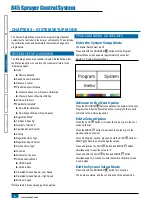
Страница 9: ...button The console will initially display the software version at the top of the screen and the serial number of the console at the bottom of the screen After approximately 3 seconds the console will...
Страница 10: ...e to the Next Option Press the PROGRAM button to advance the system to the next Program step After the final setup option is complete the console will return to the initial setup option Edit a Setup O...
Страница 11: ...to another power source Connect the battery terminal rings to the battery posts making sure that the positive red and negative black wires correspond with the polarity of the battery terminals NOTE Th...
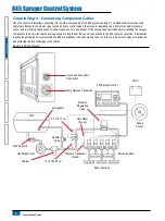
Страница 12: ...he valve and sensor leads before installing the sprayer components to be sure the cables are long enough in length from the sensor connections to the 845 console connection If installation requires lo...
Страница 13: ...veniently secured Avoid any situation where the cables may lay in puddles or come in contact with extreme heat sources WARNING System Components should be mounted at least 3 1 m from areas of excessiv...
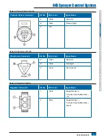
Страница 14: ...Regulating Valve and the Boom Control Valves Figure 2 5 Console Connector Console Connector Pin No Wire Color Signal Name A Blue Boom Sensor 12v Out B White Boom 1 C Brown Boom 2 D Green Boom 3 E Yell...
Страница 15: ...nal Name A White Power Out B Black Pressure Signal C N C Figure 2 9 Flow Sensor Connector Flow Sensor Connector Pin No Wire Color Signal Name A Brown Power Out B White Flow Signal C Green Sensor Groun...
Страница 16: ...le Rate Simulated Ground Speed Low Speed Simulated Ground Speed High Speed Minimum Speed Not available if a lane spraying unit is selected PROGRAM MENU GUIDELINES Enter the System Setup Mode The Maste...
Страница 17: ...per square inch gallons per acre miles per hour LM2 bar liters per 100 square Meters kilometers per hour GLM psi gallons per mile miles per hour Lane spraying LKM bar liters per kilometer kilometers...
Страница 18: ...alibration Mode press the PLUS button until a number is displayed Distance Counter The Distance Counter step is not a calibration step It is a help function that can be used to measure a distance such...
Страница 19: ...o not change the value to 0 even if there is no pressure sensor installed The Maximum Pressure cannot be set lower than the Minimum Pressure The Minimum Pressure defaults to 10 psi 0 6 bar below this...
Страница 20: ...value and initiate the calibration procedure 2 Engage the sprayer pump 3 Turn the boom sections on and begin spraying a predetermined volume of fluid i e 100 gallons 300 liters As the predetermined a...
Страница 21: ...can be located in the flow meter manufacturer s literature Regulation Mode This step is only available when both a Flow Meter and a Pressure Sensor are installed This step is automatically set to Flo...
Страница 22: ...vary with each batch and it may change due to weather humidity etc To accommodate for this the console uses a density factor to compensate for the nature of the applied fertilizer Density factor is ac...
Страница 23: ...Speed Factor can be adjusted to optimize system performance If the valve searches for the programmed application rate by cycling the pressure up and down continuously reduce the Fine Adjustment Facto...
Страница 24: ...nformation from the GNSS receiver it uses that information for determining vehicle speed If the console loses communications for more than 5 seconds it will revert to other sources of speed input If c...
Страница 25: ...e work screen without the machine in motion and the Master Switch in the ON position While pressing and holding the PROGRAM button press and release the MINUS button simultaneously for low simulated s...
Страница 26: ...For assistance with an option in the OEM menu contact customer service for assistance OEM options include Minimum Regulating Valve Voltage Regulation Dead Band Regulation Time from Minimum to Maximum...
Страница 27: ...ext Option Press the PROGRAM button to advance the system to the next Program step After the final setup option is complete the console return to the initial setup option Edit a Setup Option Press the...
Страница 28: ...set to NH3 or lane spraying GLM or LKM The speed field will be blank The console will calculate what the pressure must be to maintain the target application rate at the entered speed If the pressure i...
Страница 29: ...LKM The Tip Nozzle indicator will not be available The console will show the reference flow for the selected Tip Nozzle Figure 4 7 Known Tip Nozzle Capacity Table 4 1 Tip Nozzle Sizes and Associated C...
Страница 30: ...ode G Section Number Setup mode H Target Application Rate active I Valve Setup mode J Pressure Displays current pressure K Application Rate L Speed displays the current speed when GNSS speed is availa...
Страница 31: ...Master Switch to ON 8 Adjust the pressure with the PLUS button and or MINUS button 9 While spraying adjust the pressure with the button to the system s minimum point 10 Now press the PLUS button for t...
Страница 32: ...usual vehicle speed for spraying Moderate changes in vehicle speed will not affect the application rate because such changes are compensated by automatic pressure increases or decreases If for any rea...
Страница 33: ...the selection and exit to normal work screen Figure 5 3 Tank Level Clear Counters The Clear counters menu is used to reset the total area total volume and total distance counters to zero To clear the...
Страница 34: ...automatic regulation is stopped it will appear that the rate value changes when the speed is changed NOTE Access to manual mode may be blocked completely in OEM menu 1 Use the AUTO MAN button to switc...
Страница 35: ...Regulator Indicator Automatic Power Down The console is designed to power itself off after 10 minutes of inactivity or at the time specified in the Automatic Power Down setting in the OEM Setup Mode...
Страница 36: ...no speed alarm is triggered and spraying is stopped Medium Priority 2 short beeps repeated every second No Flow Alarm If no flow Pulses are received with master on and flow meter installed a no flow...
Страница 37: ...ensor installed will compare the actual measured pressure with the calculated pressure based on flow and Tip Nozzle type No audible alarm Flow Difference Warning With pressure based regulation the con...
Страница 38: ...o 2 No 3 No 4 No 5 No 6 No 7 No 8 No 9 Density Regulation Valve Type Regulation Speed Factor Section Valve Type Tank Size Minimum Tank Level Communication Mode GNSS Speed Variable Rate Simulated Groun...
Страница 39: ......
Страница 40: ...www teejet com 845 SPRAYER U S E R M A N U A L 98 05349 ENUS A4 LT R0 English TeeJet Technologies 2021...