


Installation and Reference Manual
System Operation
Installation and Reference Manual v3.2/0410/6
45
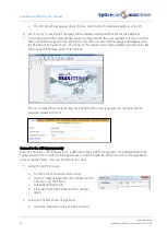
The Product Version field will display which version of software is currently running on the Trunk Module.
For information on upgrading this software please refer to page 260.
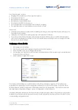
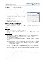
Setting the IP Address of the Trunk Module
When connecting a Trunk Module to the system for the first time a DHCP server is required to give the
Trunk Module an IP address. This address can be viewed within the Trunk Module’s configuration form
as described above. However once connected the Trunk Module can be given a static address as
follows:
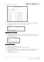
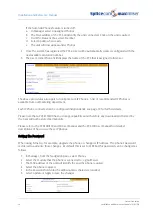
1
In Manager select Modules
2
Select the Trunk Module (SpliceGateway)
3
Within the IP Address field enter the IP Address to be used by the Trunk Module.
4
Select Update or Apply when ready
5
Reboot the Trunk Module (please refer to page 255 for information on how to reboot a Trunk
module.)
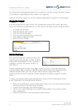
A list of each module’s IP address can be viewed in Manager by selecting Utilities and then IP Addresses.
Each port on the Trunk Module can now be configured independently, please refer to Working with
Trunks on page 159 and Creating a WAN Link on page 247 for further details:
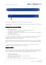
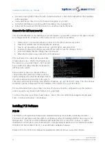
Connecting a Voice Compression Module
The 4400 Voice Compression Module provides 16 channels, of 8kbps, G.729a based compression and can
be deployed to provide a higher density of calls between Call Servers over low speed WAN links.
Additional channels of voice compression can be enabled via a licence – giving a maximum of 32
compression channels per module (please refer to the Licensing section on page 35 for further
information). By using a standard LAN for interconnectivity between the Voice Compression Module and
its associated Call Server, there is no limit to the number of compression channels that can be practically
deployed. This allows multiple 4400 Voice Compression Modules to be used with single or multiple Call
Servers, with the compression channels being dynamically allocated as, or when, required.
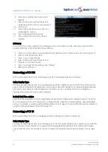
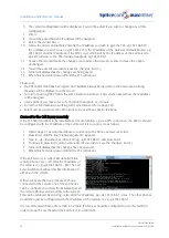
1
Connect the VCM to the system via the LAN port on the front of the VCM Module. This can be
either via the network or directly to a LAN port on the Call Server.
2
Power up the VCM.
3
The module will request an IP address from a DHCP server. It will make 4 attempts and then back
off for a period before trying again. The back off period will extend for each failed attempt.
4
Having obtained an IP address the module broadcasts to find a Call Server to provide its
configuration and become active.
5
The SpliceCom LED will become solid when the unit is ready.
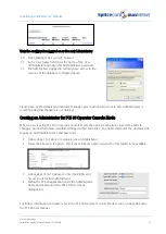
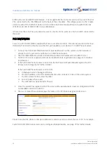
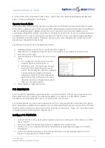
6
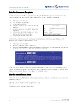
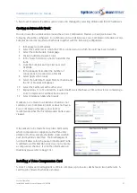
In Manager, select Unassigned Modules
7
The VCM will be displayed together with its MAC address
8
Select this link
9
The Module Status field will display “Available”
10
From the Module Status list box select “Member”
11
Select Update or Apply when ready
12
This unit will now be listed under Modules
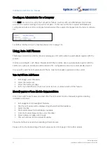
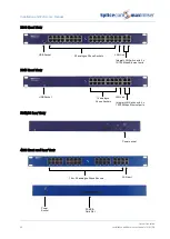
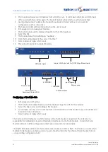
LAN Port
Содержание Maximiser
Страница 1: ...Installation Reference Manual Version 3 2 April 2010 ...
Страница 6: ......
Страница 363: ......


