background image

Guide for HD5 Assembly


OPSMN011            Rev 3


Dated: 29.06.2022 

23 

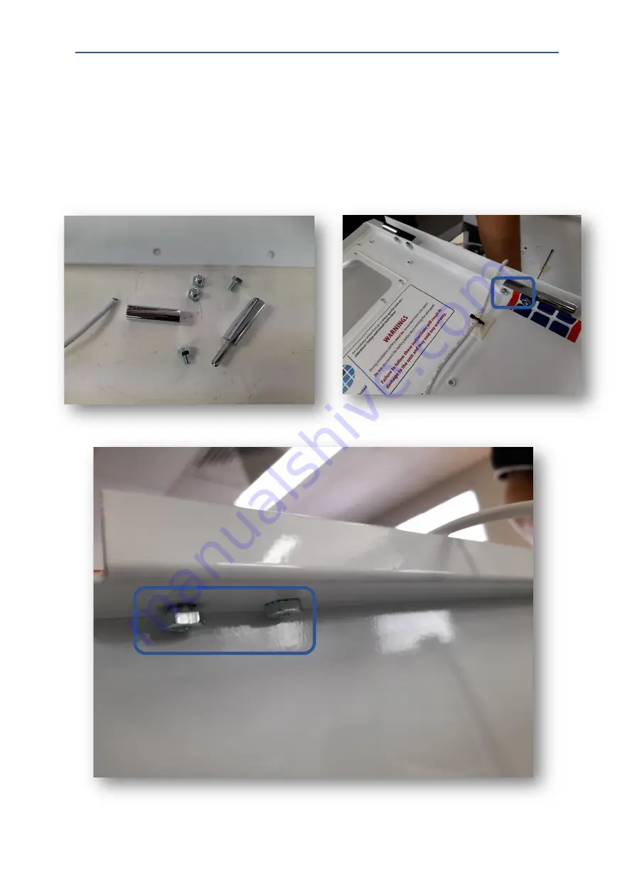
Step 8: 

Open the door assembly kit. It should contain 8 bolts and the mounts for the door. To attach the 

door first attach the mounts with the pole sticking out. Both should be facing towards the centre. 

Slide the other half over the newly attached mount, then attach the door to the other half. 


Содержание HD5

Страница 1: ...Document No Author Revision Review Date OPSMN011 M Dyson 1 6 12 21 OPSMN011 M Dyson 2 22 01 22 OPSMN011 M Dyson 3 29 06 22 HD5 Assembly Guide ...

Страница 2: ...p 3 5 Step 4 6 Step 5 6 Bottom Cover assembly 7 Materials 7 Step 1 7 Step 2 8 Step 3 8 Step 4 8 Solar Assembly 9 Materials 9 Step 1 9 Step 2 10 Router assembly 11 Materials 11 Step 1 12 Step 2 12 Door assembly 13 Materials 13 Step 1 14 Step 2 14 Step 3 15 Step 4 15 Step 5 16 Step 6 16 Step 7 17 Step 8 17 Full Assembly 18 ...

Страница 3: ... Materials 18 Step 1 19 Step 2 19 Step 3 20 Step 4 21 Step 6 21 Step 7 22 Step 8 23 Step 9 24 Step 10 24 Step 11 25 Step 12 25 Step 13 26 Step 14 26 Step 15 26 Step 16 27 Step 17 27 Step 18 28 Step 19 28 Step 20 30 Step 21 31 Step 22 31 Step 23 32 Step 24 32 ...

Страница 4: ...022 4 Top Cover Assembly Materials Item Quantity M24 Washers 2 M24 Nuts 2 M4x10 Bolt 4 Door Cover 1 Brass solar gland 1 Solar Gland 1 Solar Plug 1 Nut Clip 1 Top Cover 1 Step 1 With the thread on top screw the Brass solar gland into the top of the cover ...

Страница 5: ...ide for HD5 Assembly OPSMN011 Rev 3 Dated 29 06 2022 5 Step 2 Secure on both sides with 2 M24 washers and 2 M24 Nuts And add nut clip Step 3 Using 4 M4x10 bolts to attach the Door cover Tighten until firm ...

Страница 6: ...olar plug and the solar gland Remove the nut from the bottom of the plug securer and place it over the solar plug as shown in the image below The nut can be discarded it has no use Step 5 Feed the wire plug from the top of the cover and secure it in place with the solar gland ...

Страница 7: ...022 7 Bottom Cover assembly Materials Item Quantity M4x10 Bolt 10 M6x20 Bolt 2 M6 Spring Washer 2 M6 Nut 2 M6 Washer 2 Battery Base 1 Bottom Cover 1 Type 4 gland 2 4pinh female chassis plug 1 Base grill 1 Step 1 Secure the Base Grill using 4 M4x10 bolts ...

Страница 8: ... M6 spring washer then a M6 nut Step 3 Place the glands as shown below and secure with the previously removed nuts Attach the 4 pin female chassis plug such that the plug is on the outside of the cover Secure the chassis plug with 2 M3x10 bolts Step 4 Using 6 M4x10 Bolts attach the battery base to the cover It should be positioned as shown below ...

Страница 9: ...ated 29 06 2022 9 Solar Assembly Materials Item Quantity Solar Bracket 1 Solar Charge Controller 1 M4x6 Bolts 4 O droid 1 Step 1 Attach the Solar charge controller to the Router bracket using 4 M4x6 bolts It should be oriented as shown below ...

Страница 10: ...Guide for HD5 Assembly OPSMN011 Rev 3 Dated 29 06 2022 10 Step 2 Attach the O droid board by removing the washers at the bottom of the board lining up the bolts as shown below and tightening them ...

Страница 11: ...1 Router assembly Materials Item Quantity Spectur Camera 4k or 3 4mp 1 Router Bracket 1 Wifi Antenna 1 Mobile antenna 2 Router Teltonika RUT240 1 M4x20 Bolt 1 M4x10 Bolt 2 M4 nut 4k camera only 1 4k camera mount 4K camera only 1 M6x10 Button head SOC screw 1 ...

Страница 12: ...tach the wi fi antenna to the router by screwing it onto the plug labelled WIFI Step 2 Attach the Spectur camera to the front of the Router bracket with an M4x20 bolt through both the bracket and the camera base This process is the same for both 3 4mp and 4k cameras For the 4k Camera there will be a usb a to usb c cable that connects the camera to the watchdog ...

Страница 13: ... Dated 29 06 2022 13 For The 4k camera attach the camera to the camera mount using the M6x10 SOC button head screw Then feed the M4x10 bolt through the frame and secure on the other side with a M4 nut Door assembly Materials Item Quantity ...

Страница 14: ...t 13 Visor 1 Sticker 4 Lock 12 PIR 2 4 5mm Grommet 2 PIR Cover 2 M4x10 bolt 4 Zip tie 1 Cable management adhesive 1 Step 1 Using 8 M4x6 bolts attach the window to the back of door frame as shown below Step 2 Using 5 M4x6 bolts attach the visor to the front of the door frame as shown below ...

Страница 15: ...shown below then apply the sticker evenly across the door Use a squeegee to get any bubbles out from under the sticker Step 4 Apply the Spectur logo sticker to the front of the system as shown below Ensure hands are clean when applying this sticker as fingerprints and dirt will be visible on the sticker if they are not ...

Страница 16: ...ke a hole in the sticker where it covers the hole Before placing the cover on the PIR ensure that the PIR is facing forward and it is angled 45 degrees pointing down To secure the cover place it over the PIR and tighten the screw Step 6 On the back of the door place a 5mm grommet over the PIR cable and insert it in the hole at the bottom of the cable ...

Страница 17: ...back of the door as shown below Remove bubbles with the squeegee Step 8 Attach the lock to the door To attach remove the nut from the bottom of the lock insert the lock through the hole then replace the nut Slightly bend the latch down to stop the door from shaking when installed in the main system ...

Страница 18: ...m Quantity M4x10 Bolt 16 Zip tie Mobile extension cable 2 Ethernet cable 1 5mm Grommet 1 Router power cable 1 Battery cable 1 Mounting Bracket 1 M4x12 Bolt 2 Solar Assembly 1 cable management adhesives 10 Door Assembly 1 M6x10 Bolts 11 Load Cable 1 10 way plug 1 M6x12 Bolt 6 Door Stop 1 ...

Страница 19: ...v 3 Dated 29 06 2022 19 Step 1 Line up the Solar Assembly such that it is in line with the four holes on each side Then attach the hinge with 2 M4x10 bolts Step 2 Using 8 M4x10 bolts secure the Solar assembly on both sides with 4 bolts ...

Страница 20: ...Guide for HD5 Assembly OPSMN011 Rev 3 Dated 29 06 2022 20 Step 3 Attach 8 cable management adhesives to the inside of the camera box frame as shown below ...

Страница 21: ... the cable management adhesives for future use Step 6 Attach the two mobile extension cables to the side of the box by removing the washers and replacing them on the other side Then using a zip tie zip tie the two extension cables together and tuck them to the side of the O droid board ...

Страница 22: ...Guide for HD5 Assembly OPSMN011 Rev 3 Dated 29 06 2022 22 Step 7 Attach the ethernet cable to the O droid board and arrange as shown below ...

Страница 23: ...e door assembly kit It should contain 8 bolts and the mounts for the door To attach the door first attach the mounts with the pole sticking out Both should be facing towards the centre Slide the other half over the newly attached mount then attach the door to the other half ...

Страница 24: ... 24 Step 9 Attach the bottom cover using 4 M4x10 bolts The cover should be inside the frame and should be as shown below Attach the door stop Shown in the right image using 2 M4x12 bolts Step 10 Using two of the zip ties zip tie the PIR cable from the door ...

Страница 25: ...stem place a grommet as shown below Then proceed to attach the speaker using 3 M6x10 bolts as shown below Insert the speaker cable through the grommet Step 12 Using 2 M4x10 bolts attach the hinge to both the router bracket and the solar assembly Refer to the image below as to how to conduct the step ...

Страница 26: ...e in length Then strip off the coverings of both wires Then connect it to the teltonika Step 14 Attach the mobile extension cable to the router as shown below and the patch cable and power cable Step 15 Attach cable management adhesives to the back of the router bracket and insert a zip tie in each ...

Страница 27: ...ep 16 Zip tie the Ethernet router power camera usb and mobile extension cables Plug the ethernet into the router and the O droid board then plug the blue usb cable into the o droid board Step 17 Attach the load cable to the solar charge controller as shown below ...

Страница 28: ... floodlight power cable and the black cable from the PIR 3 Solder together the black cable from the router power cable and the black cable from the load cable 4 Solder the tips of the other wires as shown below Step 19 1 Insert the 10 pin green plug into the o droid then Insert one of the wires from the speaker in slot 1 no polarity either works Place the other speaker wire in slot 2 ...

Страница 29: ...nsert the red cable from the flood light power cable into slot 5 4 Insert the red cables from the PIR and the router power cable into slot 6 5 Insert the white cable from the PIR into slot 7 6 Insert the black cables from the router power cable and the load cable in slot 9 7 Insert the red cable from the load cable in slot 10 Make sure to tighten the flat head screws on top of each of the slots 1 ...

Страница 30: ...5 Assembly OPSMN011 Rev 3 Dated 29 06 2022 30 Step 20 Attach the battery cable to the solar charge controller The red cable should go in the 3rd slot while the black is in the 4th The order matters due to polarity ...

Страница 31: ... M4x10 bolts 4 on the front and back 3 on each of the sides Step 22 Attach the solar panel cable to the solar charge controller as shown below Continue cable management by folding and attaching the cables to the side of the router bracket with the use of previously placed zip ties Follow the image below ...

Страница 32: ...ch the mounting bracket using 4 M6x12 bolts on the bottom row and 10 M6x10 bolts for the rest of the holes in the bracket Blue is for M6x10 red is for M6x12 Step 24 Apply the Made in Australia sticker on the left side of the box With the completion of this step the HD5 system assembly is complete ...

Страница 33: ...Guide for HD5 Assembly OPSMN011 Rev 3 Dated 29 06 2022 33 ...

Отзывы: