


Operating
Instructions
12
1096.0833 | CY, CSY, LNY, LSY, NPY, PY, Y, YS Series
05/2011
5
Set-up and connection
For aggregates in potentially explosive areas
(
ATEX additional instructions)
CAUTION
Risk of material damage caused by contamination!
►
Do not remove transport locks until immediately before
setting up the aggregate.
►
Do not remove covers, transport and sealing caps until
immediately before connection
of
the
pipes to
the
aggregate.
5.1 Preparing set-up
5.1.1
Checking ambient conditions
►
Make sure the required ambient conditions are maintained
(
Ambient conditions, page 28).
►
For pump/aggregate set-up at an altitude of > 1000 m
above sea level, consult the manufacturer.
5.1.2
Minimum clearances for heat dissipation
Minimum clearances (
Clearances for heat dissipation,
5.1.3
Preparing installation site
►
Make sure the installation site meets the following condi-
tions:
the aggregate is freely accessible from all sides
sufficient space for installing/disassembling the pipes as
well as for maintenance and repair works, particularly for in-
stallation/disassembly of the aggregate, is provided for
the aggregate is not exposed to external vibrations (bearing
damage)
frost-free
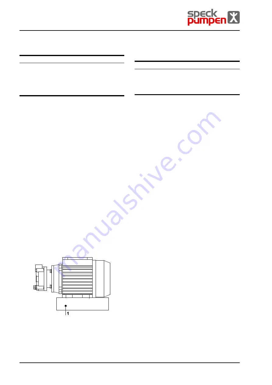
5.2 Set-up on torsion-resistant level
surface/frame
Installation position: horizontal, outlet nozzle either vertical
or horizontal (for other installation positions, please contact
the manufacturer)
Auxiliary means, tools, material:
−
wrench
1 Surface/frame
Fig. 5
Set-up on level surface/frame
1.
Position the aggregate on a torsion-resistant level sur-
face/frame (1).
2.
Screw the aggregate to the surface/frame (1) without over-
tightening the screws.
It is recommendable to position the motor on dampers to
avoid noise and vibration caused by mechanic components.
5.3 Planning pipe system
5.3.1
Dimensioning supports and connections
CAUTION
Risk of material damage if the pipes apply excessive forces
and torques to the aggregate!
►
Make sure the permissible values are complied with
(
DIN ISO 9908).
1.
Calculate the piping forces and observe all operating condi-
tions:
−
cold/warm
−
empty/filled
−
depressurized/pressurized
−
position changes
2.
Do not transmit piping forces and torques into the aggre-
gates.
3.
Make sure the pipe supports (if available) have permanent
low-friction properties and do not seize up due to corrosion.
4.
Make sure the pipes are able to wothstand the hydraulic
pressures and the temperature of the medium to be
pumped.
5.3.2
Specifying nominal diameter
Size of suction/pressure connections
(
Operating connections, page 27)
►
Keep the flow resistance in the pipes as low as possible.
1.
Nominal suction pipe diameter
≥ nominal suction conne
c-
tion diameter
2.
Nominal pressure pipe diameter
≥ nominal pressure co
n-
nection diameter.
5.3.3
Specifying pipe lengths
►
It is recommended to provide for a calming section of
A
≥ 10 x nominal inlet nozzle width
upstream the inlet nozzle
If technically possible, observe the recommended minimum
values (A) when installing the pump.
1.
Dimension the suction pipe as short as possible.
2.
For suction lift mode under ambient pressure, do not install
the pump higher than 1 m above the max.liquid level of the
reservoir.
3.
When changing the diameter, use off-centre transition
pieces to prevent formation of gas bubbles.
5.3.4
Changes in cross-section and direction
1.
Avoid radii of curvature of less than 1.5 times the nominal
pipe diameter.
2.
Avoid major changes of cross-section and direction along
the piping.
3.
To keep the flow resistance in the pipes as low as possible,
the number of installations should be reduced to a mini-
mum.


