


16
ID# M88604C1
08/06
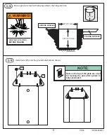
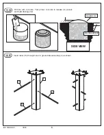
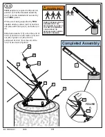
14.
A.
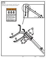
15.
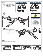
Apply height indicator
labels (32 & 31) to height
indicators (30).
2.
4.
3.
1.
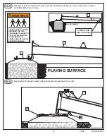
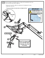
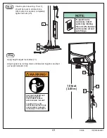
Install net (4) to rim as shown.
7 8 9 10
7 8 9 10
7
8
9
10
7
8
9
10
Set-up For Right Side
Set-up For Left Side
32
31
30
30
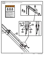
B.
Attach height indicators to lower yoke in area shown by turning
screws (29) into place with a phillips-head screwdriver.
IMPORTANT!
NOTE ORIENTATION
OF HEIGHT
INDICATORS:
10’ MARK SHOULD
FACE AWAY FROM
BACKBOARD.
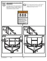
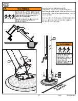
C.
Attach height indicators
to lower yoke in area
shown by turning
screws (29) into place
with a phillips-head
screwdriver.
7
8
9
10
7 8
910
29
29