7
07/06
ID# M8809511
9.
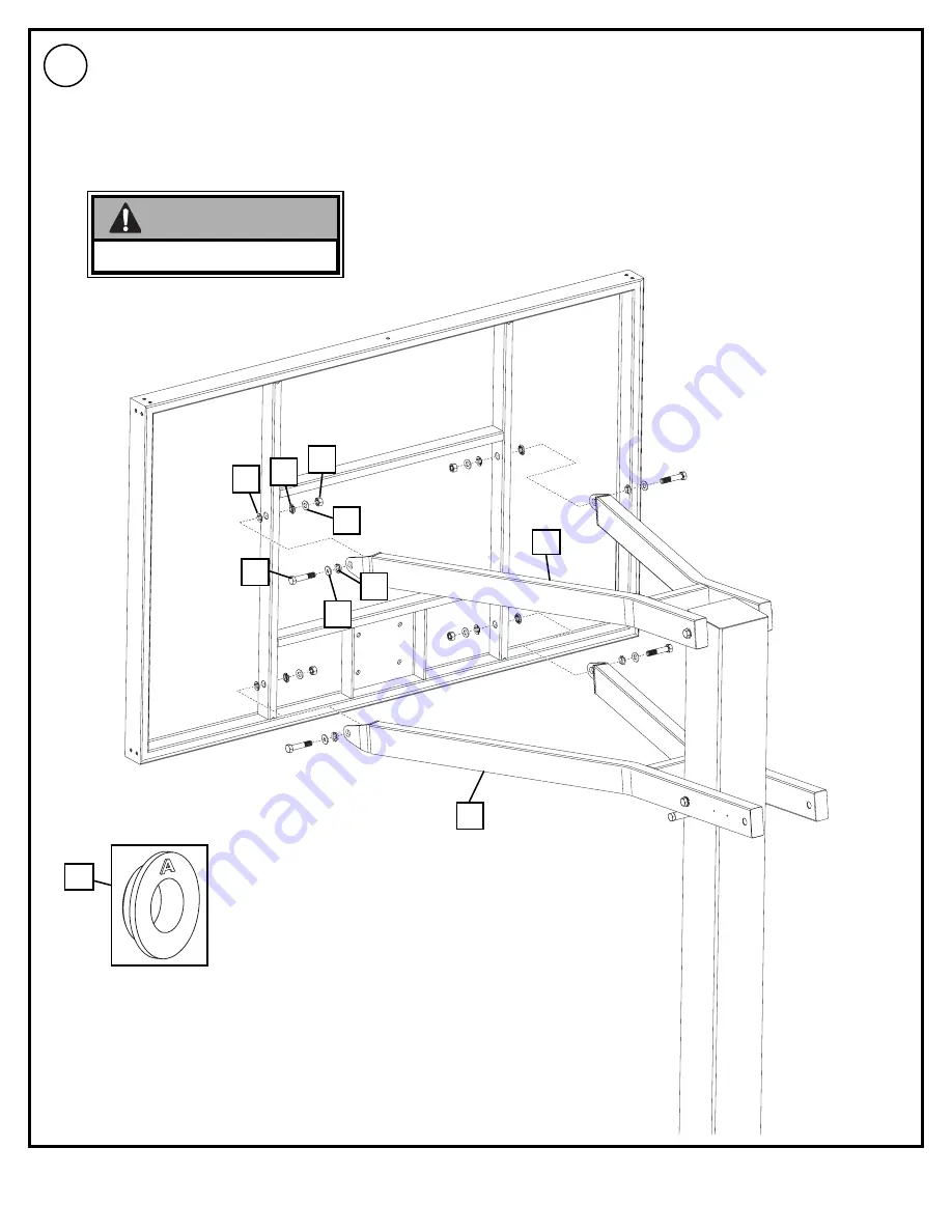
IMPORTANT!
Do Not Over Tighten.
8
14
13
27
10
9
Secure backboard to support arms (8 and 9) as shown.
Use same hardware combination for attaching both elevator tubes to thebackoard.
Страница 1: ...Number for U S 1 800 558 5234 Canada Only 1 800 284 8339 Internet Address http www hydra rib com REQUIRED TOOLS AND MATERIALS 3 Capable Adults Carpenter s Level 15 Tape Measure Shovel Post Hole Digger Phillips Screwdriver 1 Utility Knife 2 Stepladders 8 ft 2 4 m Safety Goggles Container to Mix Optional Large Small Adjustable Wrenches 2 each Wrenches and or Socket Wrenches and Sockets Deep Well Soc...
Страница 2: ... this operation Seat the pole sections properly Failure to do so could allow the pole sections to separate during play Before digging contact utility company to locate underground power cables gas and water lines Ensure there are no overhead power lines within 20 ft 7 m radius of pole location Climate corrosion excessive use or misuse could result in system failure If technical assistance is requi...
Страница 3: ...ting plate 3 and secure as shown 2 3 2 2 2 1 3 1 Install nut 2 to J bolt 1 as shown Repeat procedure for other three J bolts 1 2 1 2 6 35 cm CONTACT UTILITIES BEFORE DIGGING WARNING IMPORTANT Make sure nuts are 2 1 2 6 35cm from top of J Bolts Make sure J bolts 1 are in the illustrated position NOTE Nuts on the top of plate are used for leveling the pole after system is fully assembled NOTE ...
Страница 4: ...essure to level mounting plate on top of drainage hill Level mounting plate and square with playing surface Clean off any excess cement on mounting plate at this time 4 5 PLAYING SURFACE 3 1 IMPORTANT Front of mounting plate 3 must be parallel with playing surface WARNING DO NOT PROCEED UNTIL CONCRETE HAS CURED A MINIMUM OF 72 HOURS ALLOW ADDITIONAL TIME FOR COLD WET OR HUMID WEATHER IMPORTANT Che...
Страница 5: ... 2 Secure pole 5 flange to mounting plate 3 as shown Tighten completely 6 7 5 3 2 6 6 6 2 6 2 6 1 1 5 THREE PEOPLE REQUIRED FOR THIS PROCEDURE FAILURE TO FOLLOW THIS WARNING COULD RESULT IN SERIOUS INJURY AND OR PROPERTY DAMAGE WARNING Holes in pole must be parallel with playing surface IMPORTANT PLAYING SURFACE Position crank jack mounting as shown NOTE 6 2 6 6 ...
Страница 6: ...FOR THIS PROCEDURE FAILURE TO FOLLOW THIS WARNING COULD RESULT IN SERIOUS INJURY AND OR PROPERTY DAMAGE WARNING Beginning with upper support arm 8 secure support arms to pole Continue by securing lower support arm 9 as shown IMPORTANT Do Not Over Tighten 27 27 27 27 13 12 14 8 9 13 27 27 ...
Страница 7: ... 06 ID M8809511 9 IMPORTANT Do Not Over Tighten 8 14 13 27 27 10 13 27 27 9 Secure backboard to support arms 8 and 9 as shown Use same hardware combination for attaching both elevator tubes to the backoard ...
Страница 8: ...ounting bracket as shown 21 21 11 11 REAR VIEW 13 13 14 Position U joint of crank jack 20 as shown Where tubes on crank jack join hold steady to keep both tubes from rotating Rotate handle clockwise on crank jack to the fully extended position NOTE 20 IMPORTANT Hold Here ...
Страница 9: ...OULD RESULT IN SERIOUS INJURY AND OR PROPERTY DAMAGE WARNING 12 14 27 27 13 27 27 13 REAR VIEW IMPORTANT Do Not Over Tighten 9 9 20 20 27 A Replace spacer in jack 20 with spacer 4 Insert through top of screw jack 20 as shown B Install crank jack 20 U joint to lower support arm 9 as shown 20 4 A 20 ...
Страница 10: ...nk jack and bushings to jack brackets 21 NOTE REAR VIEW TWO PEOPLE REQUIRED FOR THIS PROCEDURE FAILURE TO FOLLOW THIS WARNING COULD RESULT IN SERIOUS INJURY AND OR PROPERTY DAMAGE WARNING 13 Rotate jack handle until jack 20 aligns with jack brackets 21 Secure crank jack 20 to jack brackets 21 as shown ...
Страница 11: ...rs 16 Attach height indicators 16 to lower arm in areas as shown by turning screws 17 into place with a phillips screwdriver 14 A B IMPORTANT Note Orientation of Height Indicators 10 Mark Should Face Away From Backboard 7 8 9 10 7 8 9 10 7 8 9 10 7 8 9 10 Set up For Right Side Set up For Left Side 19 18 16 16 ...
Страница 12: ...h rim Rim Assembly 16 IMPORTANT Carefully cut and peel protective film away from board prior to attaching rim Remove rim cover prior to installing rim assembly to board Refer To Instructions Included With Rim Hardware For Rim Assembly B D C A 15 Install net 30 to rim as shown 30 30 24 23 25 26 25 ...
Страница 13: ...TION RIM HEIGHT IS 10 FEET 3 05 m 31 17 Check leveling at this time Pole 5 should be level in all directions After system is leveled completely tighten nuts 2 above pole flange If adjustment is necessary adjust system by rotating the nuts 2 between mounting plate 3 and pole flange NOTE 5 2 ...
Страница 14: ...handle to raise or lower backboard 20 Secure pole pad 32 as shown 19 32 Height Adjustment If height adjustment is difficult to operate you may have over tightened the areas indicated NOTE Pole pad may NOT be included in this model NOTE ...
Страница 15: ... 1 2 14 11 206340 Lock Nut Hex 1 2 13 15 2 205082 Spacer 0 53 I D x 0 75 O D x 38 Long 16 2 204735 Height Indicator 17 4 204733 Screw 8 x 050 Long Item Qty Part No Description 18 1 204739 Label Height Indicator Right 19 1 204740 Label Height Indicator Left 20 1 222880 Crank Jack 21 2 908292 Bracket Crank Jack Support 22 4 205702 Nut Hex 3 8 16 23 2 205701 Bolt Carriage 3 8 16 x 3 5 Long 24 2 20570...
Страница 16: ...6 Item 26 4 Item 27 28 Item 7 2 Item 15 2 You May Have Extra Parts With This Model Item 14 11 Item 2 12 Item 13 20 Item 22 4 Item 6 8 HARDWARE IDENTIFIER NUTS WASHERS STEEL SPACERS HARDWARE IDENTIFIER PLASTIC NYLON SPACERS Item 4 1 ...