background image

Seaich Corporation, LLC. All rights reserved. www.seaich.com | Spacerails, LLC. www.spacerails.com 

Page 19  

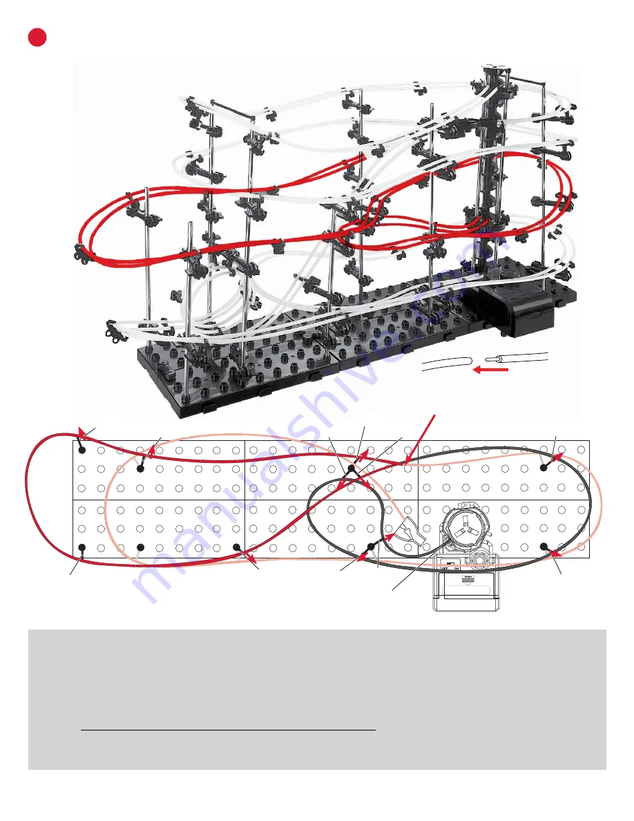
CONNECT TWO R-D RAILS AND JOIN WITH TWO R-C RAILS

D

Use the following illustrations and pictures as  

for attaching the rails to the structure:

Step 10: 

Rotate one rail arm on A-2, C-3, F-2, F-4, F-3, H-2, I-2, G-3, G-4, and E-4 to match the red arrows shown above. The 

arm number is shown above and is counted from the bottom up. 

D-3 is the 3rd arm from the bottom on the D shaft. 

Step 11: 

Connect two R-D rails starting at the middle elevator ring and going to G-3, F-3, F-2, G-4, I-2, H-2, E-4, B-2, A-2, 

C-3, F-4, and leave hanging at joint until end of Step 12. There will be extra rail at the end. Leave extra at this point.

Step 12: 

Starting at middle elevator ring, straighten rails and place a Rail Clip in between each shaft to keep rails evenly 

spaced (red triangles are not shown to help with visual clarity of the rails.) Go from section to section until you reach where 

the two sets of rails are hanging. Start by cutting one set of the rails even with each other. Then overlap the other set and 

cut so they will join evenly. Insert the rail connectors into the ends of one set, then join them with the other set.

A-

2

C-

3

F-

2

F-

3

F-

4

H-

2

I-

2

G-

4

G-

3

E-

4

B-

2

TWO R-D rails are used. (150 cm each)

Rails R-C and R-D 

will be joined here.

Middle

Elevator Ring

Содержание Level 3

Страница 1: ...not intended for children under 3 This product is intended for users 8 years of age and older To avoid choking keep small parts away from children Use caution this product contains parts with sharp edges To avoid potential damage to the product only insert the included marbles into the elevator ...

Страница 2: ...Page 2 Seaich Corporation LLC All rights reserved www seaich com Spacerails LLC www spacerails com MULTI VIEW OF FINAL ASSEMBLY LEVEL 3 FRONT BACK ...

Страница 3: ...Seaich Corporation LLC All rights reserved www seaich com Spacerails LLC www spacerails com Page 3 3 4 ANGLE TOP LEFT RIGHT ...

Страница 4: ...r A x2 Base Holder B x2 BASE COMPONENTS ELEVATOR COMPONENTS Power Box x1 Shaft 300mm x10 Shaft 200mm x3 Elevator Helix x12 Elevator Ring x3 Elevator Cover x1 Elevator Guard x2 RAIL COMPONENTS Rail Clip x45 Rail Coupling x10 Marble x3 Rail 16000 mm Rail Splitter x1 Power Box Stand x1 Shaft Connector 90mm x2 Shaft Connector 50mm x2 REQUIRED TOOLS ITEMS NOT INCLUDED Wire Cutters or Utility Scissors P...

Страница 5: ...re the Arm Clip in place Step 2 Insert Arm Lock through Arm Holder A and Arm Clip B ARMS QTY 40 To avoid damaging parts do not move or adjust the Rail Clip while locked in the arm To move the Rail Clip release Arm Lock by turning clockwise position Rail Clip as desired then secure Arm Lock again Step 1 Interlock 6 Base blocks at tabs as shown below Be sure tabs connect Step 2 Press 2 Base Holder A...

Страница 6: ...SSEMBLY Step 3 Connect 12 Elevator Helix pieces together with the male part facing up to fill the shaft Rotate each piece so the track lines up with the piece below it Step 1 Place a 300 mm shaft in the white hole on the Power Box Step 2 Install the first Elevator Helix piece male side up and rotate it until it slides in place and engages with driver at the base of Power Box Male side up Always st...

Страница 7: ...ing out because it enters fast Step 6 Install Elevator Rings with tabs facing up as shown in red above Slide each ring from the top down Place 1 ring flush with the bottom Place the other 2 at measurements shown measuring from top of the shaft to the center of the ring NOTE Illustration of shafts is not to scale Refer to separate tri fold insert for a diagram to scale if you prefer to lay parts ou...

Страница 8: ...g ruler either from top of the shaft down or the bottom of the shaft up as indicated See illustration on next page for arm attachment instructions Diagram is not to scale Use tri fold insert for an actual size diagram Front facing arm down 1 4 5 3 2 34 mm 136 mm 32 mm 87 mm 132 mm Back facing arm down 1 2 4 3 24 mm 96 mm 25 mm 1 2 3 4 5 34 mm 60 mm 85 mm 47 mm 7 mm 1 2 163 mm 68 mm 141 mm A B C D ...

Страница 9: ...ey don t rotate easily Pay attention to back front up down position of arms as shown on diagram Arm attachment Rotate position of arm to match left right up down orientation shown on diagram Attach to shaft by slightly pulling apart the open arm and inserting shaft Then insert an Arm Lock and turn to lock in place as shown below Note if you incorrectly used an Arm Holder A piece instead of an Arm ...

Страница 10: ...the shaft down or from the bottom of the shaft up as indicated See illustration on previous page for how to attach arms Diagram is not to scale Use tri fold insert for an actual size diagram F SHAFT ASSEMBLY PLACEMENT PART 2 POWER BOX PLACEMENT Shaft Top Shaft bottom F G H I Back facing arm up 1 1 1 1 2 2 2 2 3 3 3 3 4 4 4 4 5 5 6 7 6 100 mm 144 mm 120 mm 27 mm 27 mm 40 mm 50 mm 90 mm 94 mm 68 mm ...

Страница 11: ...w Pay attention to back front up down position of arms as shown on diagram Step 4 Insert the Power Box Stand into the bottom of the Power Box on the bottom of the elevator as shown below Insert C battery not included into Power Box battery compartment Attach the entire elevator to the base assembly by inserting the three posts in the bottom of the Power Box into the positions shown in the diagram ...

Страница 12: ...elow Make sure to cut at a 90 angle All of these rail dimensions include extra rail They will all need to be cut shorter based on their final placement and positioning It is easier to position with more rail than you need and then cut a long rail shorter Illustration of rail lengths is not to scale Please see the included tri fold with printed ruler for laying the rail out on a template to measure...

Страница 13: ...ms for rotation positions Rail side When installing Rails make sure you keep each rail always on the inner side or always on the outer side of each arm as you install Crossing over will prevent the Marble from going down the track Rail stability To maintain stability on longer track segments attach Rail Clips between arms usually one between each set of arms but use as needed Twisting Rail Clips a...

Страница 14: ...en Broken Arm Clip If you end up accidentally breaking an arm clip replace it with a spare If your have no more spares place a Rail Clip before or after it at the same angle as the Arm Clip Elevator exit When installing the elevator exit rails pull the rails close to the Elevator Helix to ensure the Marble enters the roller coaster smoothly Corner shape To help the Marble maintain speed shape corn...

Страница 15: ...op should be 80 mm in diameter Loop shape Make sure your loops are a nice even circle and are fully upright Use Rail Clips to help maintain shape Close up of finished space loops Note the vertical alignment shape and the two different loop sizes Also note the placement of Rail Clips Close up of finished space loops Note the vertical alignment shape and the two different loop sizes Also note the pl...

Страница 16: ...levator shaft and going left connect at G 7 D 4 C 5 F 6 H 4 I 4 and then connecting the end into the back side of the Rail Splitter Rail Splitter will hang freely and there will be extra rail at the end Leave extra rail until the end of Step 3 Step 3 Starting at the elevator shaft straighten rails and place a Rail Clip in between each shaft to keep rails evenly spaced as shown by the red triangles...

Страница 17: ...t C 2 and should be 80 mm in diameter to C 1 at D 2 it shrinks to 70 mm in diameter see page 14 loop instructions through D 1 After loop continue to E 3 G 6 and then connecting the end into the back side of the Rail Splitter There will be extra rail at the end Leave extra rail until the end of Step 3 Step 6 Starting at the elevator shaft straighten rails and place a Rail Clip in between each Shaft...

Страница 18: ... 8 Connect two R C rails starting at the right front side of the Rail Splitter and going to F 5 C 4 D 3 E 5 G 5 I 3 H 3 and leaving the rails hanging as shown These will be joined with the next set of rails There will be extra rail at the end Leave extra rail until the end of Step 12 Step 9 Starting at Rail Splitter straighten rails and place a Rail Clip in between each shaft to keep rails evenly ...

Страница 19: ... I 2 H 2 E 4 B 2 A 2 C 3 F 4 and leave hanging at joint until end of Step 12 There will be extra rail at the end Leave extra at this point Step 12 Starting at middle elevator ring straighten rails and place a Rail Clip in between each shaft to keep rails evenly spaced red triangles are not shown to help with visual clarity of the rails Go from section to section until you reach where the two sets ...

Страница 20: ...Seaich Corporation 1910 West 1040 South Salt Lake City UT 84104 833 732 4242 orders seaich com SpaceRails LLC www spaceRails com ...

Отзывы: