


Page 1
8
of
20
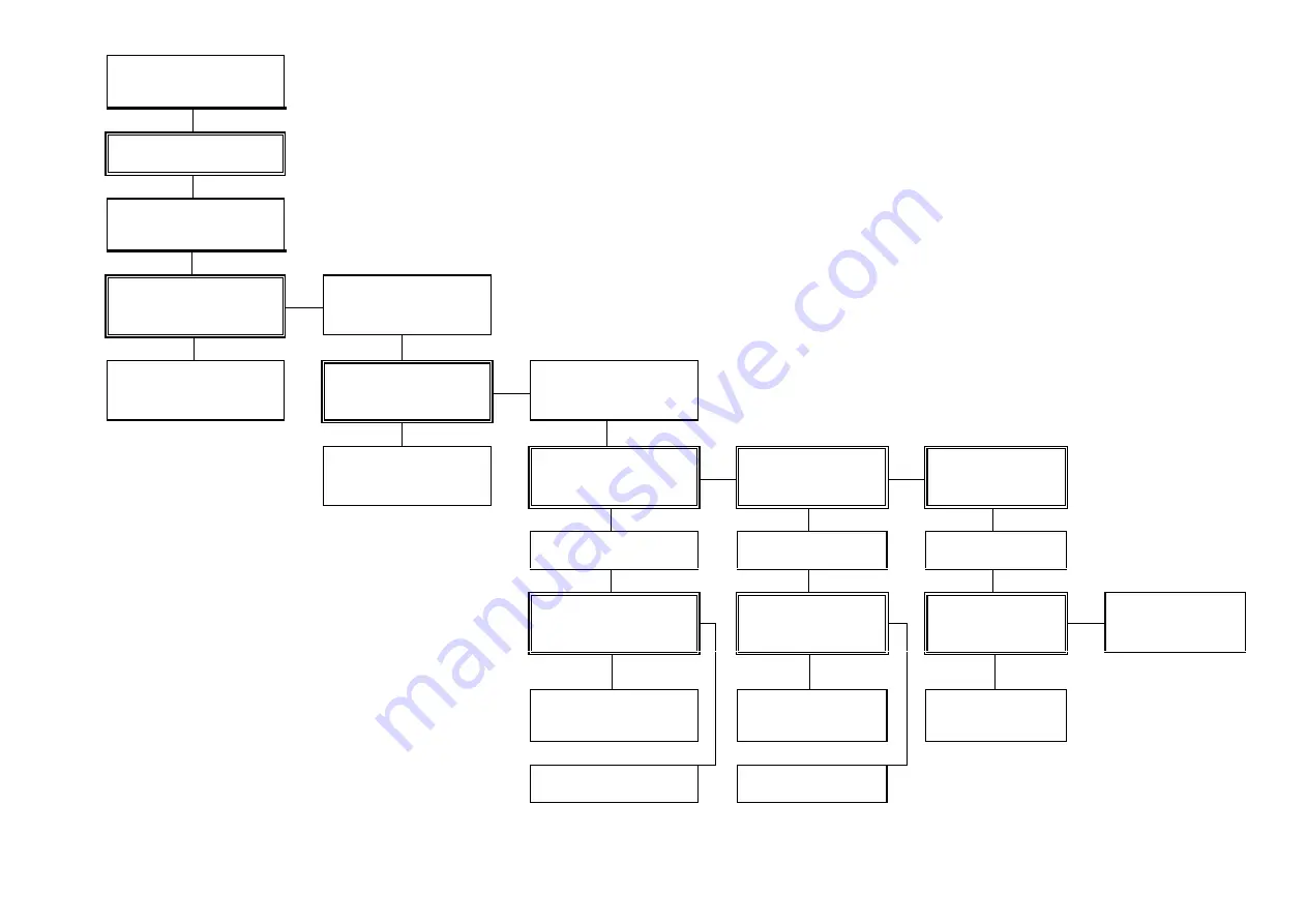
Check Gas & Electricity
supplies turned 'ON'
Set Thermostat to 'MAX'
10. FAULT FINDING CHART
Has Burner flame established
NO
Check 230V present at Ignition
Control &
circuit continuity
YES
230V at Ignition Control &
circuit continuity correct
Check gas Supply pressure at
control valve test point 'IN'
NO
YES
Rectify electricity supply or
circuit continuity
Gas Supply pressure in
accordance with section 3.2.
of manual
Check gas Setting pressure
at Control valve test point
'OUT'
NO
YES
YES
Rectify Gas Supply to the
appliance
Gas Setting pressure in
accordance with section 3.2
of manual
Is Ignition spark present at
Electrodes
Does Ignition Spark
cease when Burner
ignites
NO
NO
NO
Adjust gas Setting pressure.
Check control valve operation
Check Spark Electrode
and circuit continuity
Check Flame Rod and
circuit continuity
YES
YES
YES
Gas Setting pressure &
control valve operation
correct.
Spark Electrode & circuit
continuity correct
Flame Rod and circuit
continuity correct
Replace Ignition Control
NO
NO
NO
Replace Control Valve
Replace spark electrode &
rectify circuit continuity
Replace Flame Rod or
rectify circuit continuity
Replace Ignition Control
Replace Ignition Control
Содержание ERP10
Страница 2: ......
Страница 7: ...Page 5 of 20 Fig 1 Disclaimer Valve and control assemblies will differ on European approved heaters...
Страница 21: ...NOTES Page 19 of 20...
Страница 22: ...Page 20 of 20 09 03 GB 602S...