SPSWH.com SP Blue Solo 80 installation manual Doc
SP.
SP Blue Solo 80.E.2021.REV1.0
9
|
P a g e
4.3
Solar Thermal System Installation Instructions
4.3.1
Piping Installation
All pipes to and from the system must meet local building and plumbing codes for potable and hot water
and are supplied by the contractor. It is recommended that supply and return pipes from the home be
5/8” OD rigid copper.
All pipes should be appropriately sloped (min 4°) to ensure the lowest point is the
bottom of the collector so that in the event of system decommissioning due to maintenance etc. the
water can be appropriately drained.
See
for additional details.
The piping and insulation on the solar system from the tank to the collectors and the collectors to the
tank is flexible stainless-steel hoses of size DN16 with 9 mm of insulation and protective UV coating
included which is included with the system. This hose is connected by following the steps in the pictorial
installation manual below.
There is a Danger during any draining of the system of scalding water at high pressure
being discharged. Caution must always be taken when discharging or draining the
system.
4.3.1.1
Piping Insulation
It is recommended that mains piping to the tank and return
piping to the fixtures will be 5/8” OD copper
pipe and the recommended insulation will be ½” elastomeric foam R 3.4.
Suitable protective cover of
the insulation must be installed to prevent damage from the elements. This can be a wrap or paint or
other means to protect the installation from the elements specifically moisture and UV.
4.3.2
Safety Relief Valve (Temperature & Pressure)
Safety relief valve dis-charge pipes shall be of rigid pipe that is approved for the temperature of the
system. The discharge pipe shall be the same diameter as the safety or relief valve outlet. Safety and
relief valves shall not discharge so as to be a hazard, a potential cause of damage or otherwise a
nuisance. Relief valves in partially filled collector loops capable of producing steam shall be discharged
to the outside of the structure. Where a relief valve discharges inside a structure or to the drainage
system, the installation shall conform to the plumbing code adopted by the authority having jurisdiction
or, in the absence of such code, the International Plumbing Code. Where a solar thermal system
component requiring a relief valve is located outside the structure, the termination shall be not more
than 6 inches (152 mm) above a splash block, a secured surface material or catchment method to pre-
vent damage.
4.3.3
Operating Indicators – Temperature gauges
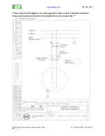
It is recommended for the system the installation of two easy to read temperature gauges on the inlet
and outlet of the system, i.e., the cold mains water to the system and hot return water from the system.
These two gauges must be easily accessible by the system operator/owner and protected from the
elements. To determine whether the solar system is working, observe the temperature gauges when the
hot water is being used. The water returning from the collector on a sunny day at noon should be 75° -


