background image

Southworth Products

DDL Dock Lift Manual

DDL Dock Lift Manual

17

6.2    Periodic Maintenance

Before each use ensure area is clear of debris and sump/drain is clear. Inspect the machine 

for excessive wear or damage and ensure all precautionary labeling is legible. Inspect railings, 

verify cables/chains are in place and in good condition. Verify push button switch and cord are 

functioning and are not damaged.

6.2.1.  Weekly Maintenance

•  Inspect leg rollers, center pivot pins and bushings, and leg hinge pins and bushings for 

excessive wear or damage. Repair or replace as necessary.

•  Inspect machine for loose of broken fasteners. Repair or replace as necessary.
•  Inspect labeling. If any label is damaged or otherwise illegible contact the manufacturer 

for replacement labels.

6.2.2.  Monthly Maintenance

•  Perform Weekly Maintenance.
•  Apply a light oil or PTFE lubricant to non-greased pivot points or rollers. 
• 

Inspect the appearance of the hydraulic fluid. The fluid should be transparent and clear 

of debris.

• 

Inspect all hydraulic hoses and fittings. Repair or replace as necessary.

•  Inspect all electrical wiring and connections. Repair or replace as necessary.
•  Inspect limit switches, if applicable. Repair, replace, or adjust as necessary. 

6.2.3.  Six Months

•  Perform Monthly and Weekly maintenance.
• 

Inspect the hydraulic cylinder and return line. If excessive fluid exists in the vent line, 

the cylinder may need to be repacked or replaced.

• 

Change hydraulic fluid. Clean the suction screen and vent cap. Replace pressure line or 

return line filter element (if equipped).

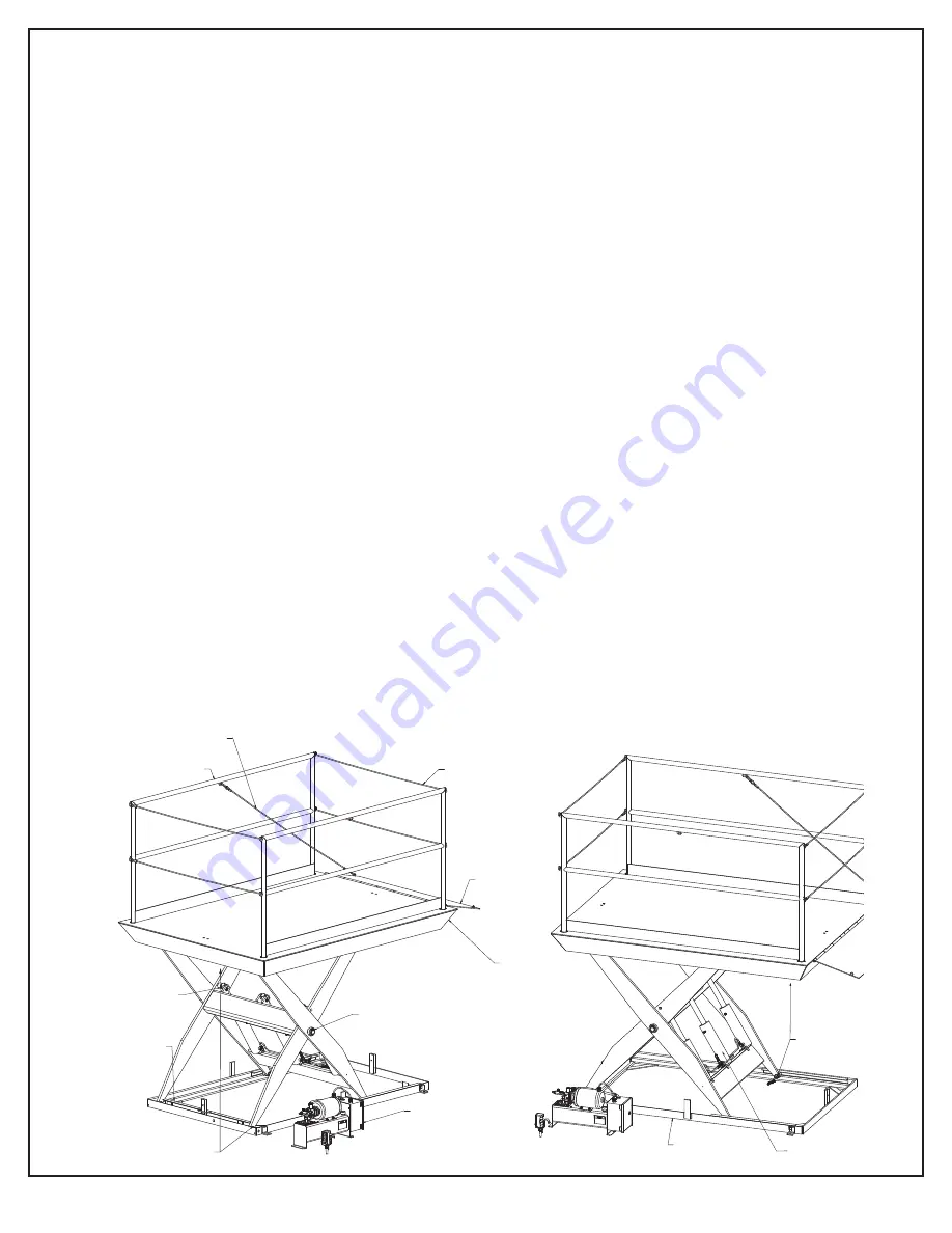
BASE FRAME

RAILINGS (BOTH SIDES)

HYDRAULIC POWER UNIT

(STOWED)

MAINTENANCE

PLATFORM)

PULL CABLE

PLATFORM

SNAP CABLES 

(BOTH ENDS OF 

DEVICE

HYDRAULIC

CYLINDER PINS

(EACH CYLINDER)

THROW OVER 

PLATE

CENTER PIVOT 

PINS/BUSHINGS

(BOTH SIDES)

UPPER/LOWER LEG HINGE 

PINS/BUSHINGS (BOTH SIDES)

UPPER/LOWER 

ROLLERS 

(BOTH SIDES)

HYDRAULIC 

CYLINDERS

Содержание DDL 5-59M

Страница 1: ...2019 Model Serial Number Date placed in service Dura Dock Dock Lift Owner s Manual DDL 5 59M DDL6 59M DL8 59M SOUTHWORTH PRODUCTS CORP P O Box 1380 Portland ME 04104 1380 Telephone 800 743 1000 207 8...

Страница 2: ...ommended Pad Plan 11 4 5 Alternative Pad Plan 12 4 6 General Installation 13 5 Operation 14 5 1 Loading 15 6 Maintenance Repair 15 6 1 Maintenance Devices 16 6 2 Periodic Maintenance 17 6 2 1 Weekly M...

Страница 3: ...mation visit www P65Warnings ca gov This lift is design and manufactured in accordance with ANSI standard MH29 1 The Safety Requirements for Industrial Scissors Lifts 9 5 Hydraulic Arrangements 24 9 5...

Страница 4: ...llowing precautions shall be taken as applicable 1 Remove the load from the load enclosure 2 Lower the platform to the full down position 3 Relieve system pressure from all circuits before loosening o...

Страница 5: ...ffecting the operation of the machine 4 Factors affecting stability 5 The purpose of placards and decals 6 Workplace inspection 7 Safety rules and regulations 8 Authorization to operate 9 Operator war...

Страница 6: ...isor any problem s or malfunction s that become evident during operation The operator shall ensure all problems and malfunctions that affect the safety of operations are repaired prior to continued us...

Страница 7: ...ed will result in death or serious injury Indicates a hazardous situation that if not avoided could result in death or serious injury Indicates a hazardous situation that if not avoided could result i...

Страница 8: ...Southworth Products DDL Dock Lift Manual 8 3 1 Label Location Diagram BK LD TAG SOUTHWORTH 5900158...

Страница 9: ...g using the maintenance device See Maintenance Devices section Use appropriate lifting device to lift the machine Use a load spreader to lift the machine Lift the machine using the provided lifting ey...

Страница 10: ...HIND CURB FRONT OF PIT ALIGNED WITH CONCRETE ANCHORS TO BOLLARDS TO BE CENTER LINE OF FROM EACH END 12 O C WITH ONE 3 1 2 X 6 LOCATED PREVENT STANDING WATER PIT DRAIN AS REQUIRED TO BE IN PIT BY CONTR...

Страница 11: ...5 6 12 7 1 2 57 6 2X 54 96 PAD NOTES CROSS HATCHING INDICATES AREAS OF BASE FRAME THAT MUST BE SHIMMED AND OR GROUTED AFTER LEVELING OF THE BASE FRAME TO ENSURE PROPER BASE FRAME SUPPORT CONDUIT RUN...

Страница 12: ...S WITH NO CONDUIT ROUTING PROVIDED 7 1 2 6 ANCHORS 57 FILLED WITH CONCRETE TYP BY CONTRACTOR 8 STEEL PIPE 96 PAD 72 PAD FRAME 78 9 7 1 2 5 2X 54 BASE 6 NOTES IF SUMP IS NOT USED THE BASE FRAME MUST BE...

Страница 13: ...and engage the maintenance device See the Maintenance Devices section Ensure the roller end of the platform is not is not lifted off of the upper rollers 5 Remove the eye bolts and save them for futu...

Страница 14: ...ic hoses and connections wiring and electrical connections and other components for proper installation and damage 14 Cycle the lift to test function If platform does not begin to raise after a few se...

Страница 15: ...WN button on the controls Release the button when the platform is at the desired height 5 1 Loading All loads should be centered on the platform Uneven loading can lead to excessive wear or damage Alw...

Страница 16: ...achine is supported by the maintenance device s Continue to hold the down button for five to ten seconds after the platform stops to relieve hydraulic system pressure 6 Disconnect electrical supply an...

Страница 17: ...E lubricant to non greased pivot points or rollers Inspect the appearance of the hydraulic fluid The fluid should be transparent and clear of debris Inspect all hydraulic hoses and fittings Repair or...

Страница 18: ...atform See General Installation Section numbers 1 5 2 Attach chains straps and load spreader to the lifting eyes 3 Using an appropriate lifting device slowly pull the chains straps until they are taug...

Страница 19: ...arranty The warranty for repair parts is 30 days from date of shipment Parts replaced under warranty are on a charge credit basis We will invoice you when we ship the replacement part then credit you...

Страница 20: ...t Customer Service for procedure Down valve may be energized Check the solenoid with a volt meter Cylinder may be leaking Check for fluid leaks Lift will not lower Down valve may not be energized Chec...

Страница 21: ...Phase Frequency Full Load Amp Required Supply Fusing 460 3 60 4 6 AMP 230 3 60 8 12 AMP 208 3 60 8 4 12 AMP M1 1 2 3 5 Sol DOWN VALVE SOLENOID 2 HPU MOTOR STARTER M1 OL 2 3 5 L1 L1 L3 L2 FUSED DISCON...

Страница 22: ...ONNECT L1 TO 208 230 460 3 60 SUPPLY VOLTAGE SEE 96 ELECTRICAL INFORMATION SECTION 1 2 3 4 5 6 VOLTAGE FROM FUSED DISCONNECT BY CUSTOMER JUMPER A ENSURE PROPER FUSES ARE USED AND OVERLOAD RELAY IS ADJ...

Страница 23: ...draulic Power Unit 9 4 Hose Specifications ADJUSTABLE FLOW TO LIFT BREATHER CONTROL PANEL PUMP PRESSURE LINE MOTOR DOWN SOLENOID VALVE CONTROL REMOVE PLUG AND REPLACE WITH VENT LINE ELBOW AND CONNECT...

Страница 24: ...achine is installed in a pit pad without an under lift conduit run for routing hydraulic hoses and electrical wiring ROLLER END FROM HPU LINE COUPLINGS FOR PRESSURE EXCESS FLOW VENT LINE CONNECTIONS P...

Страница 25: ...a s Proposition 65 Southworth Products makes no warranty or representation with respect to the compliance of any product with other State or local safety or product standard codes and any failure to c...

Отзывы: