TRAK Machine Tools
Southwestern Industries, Inc.
The ProtoTRAK DXF Converter Operating Manual
5
3.0 Using the DXF Converter for Mills
Using the DXF Converter is a matter of a few simple steps that will be described in this section.
Please set the ProtoTRAK CNC or Offline to the desired 2-axis or 3-axis mode before entering the
DXF Converter. These settings cannot be changed once the converter process has started.
Your ProtoTRAK software comes with a sample DXF part program you can use to follow along
with these instructions. This part program is named BALLPARK.DXF and it is located on the C
drive in t
he ProtoTRAK CNC in the directory called “SWI Test Programs”, within
the directory
where the main software is installed (PT4, PT4SX, or PT7). For the Offline program, the part
program is in the drive you specified when you installed the ProtoTRAK Offline on your computer.
3.1 Opening a DXF Part Program
The DXF Converter is launched automatically when you open a file with the DXF or DWG
extension.
When you select a file with an extension of .DXF or .DWG, the Open As field automatically
changes to ACAD DXF. Press Open File and the DXF Converter will begin to process the file.
Note:
You can use Mode (Alt + M in Offline) to exit DXF and return to normal ProtoTRAK
operation at any time during the DXF conversion process. This will discard any information
generated during the DXF conversion session.
3.2 Choose the Layers That You Want to be Displayed
CAD files are made for printing, not machining. Therefore, DXF and DWG files usually contain
information that is good to have on a print, but not useful for machining. Examples include
borders, writing and dimension lines. To make the DXF conversion convenient, it is helpful to
eliminate those unneeded elements of the drawing from view.
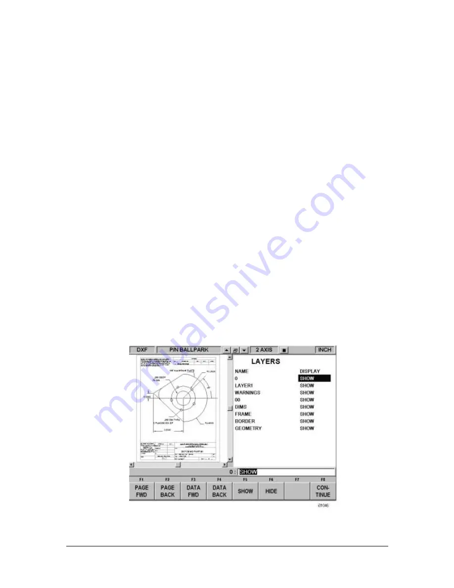
The initial screen of the DXF
converter has all the drawing’s layers visib
le. This step allows you to
Hide unwanted information so you may focus on what you want to machine. See figures below.
FIGURE 3.2.1 The first screen you see when the DXF Converter launches. Notice that the entire
drawing, including borders and dimensions, is shown on this first view.


