TRAK Machine Tools
Southwestern Industries, Inc.
The ProtoTRAK DXF Converter Operating Manual
6
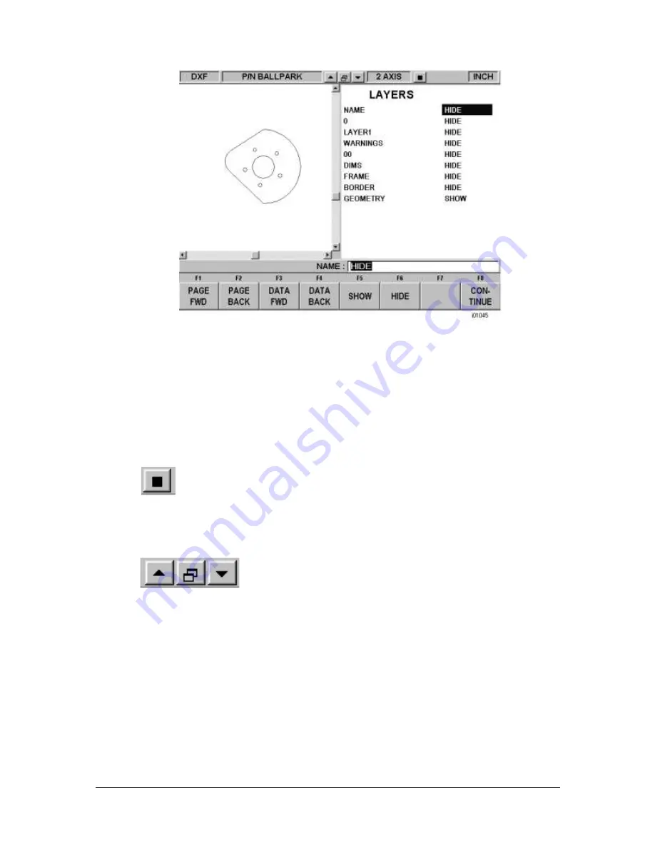
FIGURE 3.2.2 Through a process of elimination, we have isolated the view of what we want to
machine.
To choose a layer that you would like to Hide use the Data Forward key or simply click on the
layer name with the mouse. You can go between Show and Hide as often as you like as you
choose which layers to eliminate from view.
In this first screen, there are some new buttons that don’t appear
elsewhere on the ProtoTRAK.
Items unique to the DXF Converter appear in the status line at the top:
Background Selection Button.
Click on this to toggle between a
white and black background. You should use the background that
allows you to see the layers on the drawing. So that they remain visible, the
DXF Converter will automatically change the color of white lines to black or black lines to
white depending on the background you choose. Colors used in the drawing that are
other than black or white will stay the same regardless of background.
Zoom In, Zoom Out and Auto-Fit Drawing Buttons.
Press Continue when only the layer(s) you wish to remain are shown. When you leave
this screen, you may return to it by pressing the Back key (Alt + B on the ProtoTRAK
Offline). However, any additional data you have added will be lost.
3.3 The Gap Tolerance
The ProtoTRAK makes it easy to program pockets and profiles and the DXF Converter makes it
even easier by providing the dimensions. One potential problem in this process is that a CAD
drawing is made to be looked at, not machined. DXF and DWG files may contain lines or arcs that
look connected on a print, but really have tiny gaps between them. The gap tolerance of the
DXF Converter is an elegant solution to this problem. You enter a single value
–
a tolerance
–
and the DXF Converter automatically closes the gaps that are within that value while you are
programming a Pocket or Profile. If you don’t
want this done automatically, you aren’t forced to


