background image

4.

  Set fence to 90° and near front of jointer, 

so amount of exposed cutterhead in front of 

fence matches size of desired rabbet.

5.

  Start jointer.

6.

  Place workpiece firmly against fence and 

infeed table.


CAUTION:

 To ensure workpiece remains 

stable during cut, concave sides of workpiece 

must face toward table and fence.

7.

  Feed workpiece completely across cutterhead 

while keeping it firmly against fence and 

tables during entire cut.


CAUTION:

 Keep hands at least 4" 

away from cutterhead during the entire 

cut. Instead of allowing a hand to pass 

directly over cutterhead, lift it up and 

over cutterhead, and safely reposition it 

on the outfeed side to continue supporting 

workpiece. Use push blocks whenever 

practical to further reduce risk of accidental 

hand contact with cutterhead.

8.

 Repeat 

Step 7 until rabbet is cut to depth.

9.

 Re-install cutterhead guard if removed in 

Step 3.

DO NOT exceed 

1

8

" cut per pass on this 

machine or the risk of kickback and serious 

injury will be greatly increased!

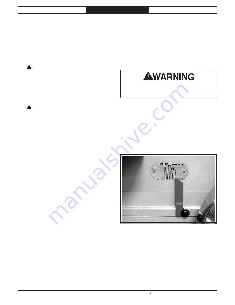
Figure 24. Model SB1091 depth scale.

South Bend Tools

For Machines Mfd. Since 10/20

Model SB1091

-29-

O P E R A T I O N

Setting Depth of Cut

The depth of cut on a jointer affects the amount 

of material removed from the bottom of the 

workpiece as it passes over the cutterhead.

The depth of cut is set by adjusting the height of 

the infeed table relative to the outfeed table and 

cutterhead inserts at top dead center (TDC).

To set depth of cut on jointer:

1.

  Loosen infeed table lock and rotate 

handwheel until depth scale on front of 

jointer (see Figure 24) indicates desired 

depth of cut.

 Note:

 The depth scale can be calibrated 

or "zeroed" if it is not accurate. (Refer to 

Calibrating Infeed Table on Page 40).

2.

  Set infeed table positive stops according to


Setting Infeed Table on Page 40.

3.

  Tighten infeed table lock before beginning 

jointer operations.

Содержание SB1091

Страница 1: ... A Tradition of Excellence South Bend Tools JUNE 2020 Revised JANUARY 2021 KS For Machines Mfd Since 10 20 V2 01 21 MODEL SB1091 8 PARALLELOGRAM JOINTER OWNER S MANUAL ...

Страница 2: ...ion is a process that happens through training and experience If you are not an experienced operator of this type of machinery read through this entire manual then learn more from an experienced operator schooling or research before attempting operations Following this advice will help you avoid serious personal injury and get the best results from your work Manual Feedback We ve made every effort...

Страница 3: ...justing Cutterhead Guard 42 Setting Fence Stops 43 Adjusting Replacing V Belt 45 Pulley Alignment 46 ELECTRICAL 47 Electrical Safety Instructions 47 Wiring Diagram 48 Electrical Components 49 PARTS 50 Fence 50 Base 51 Table Accessories 53 Stand Motor 54 Machine Labels 56 WARRANTY 57 INTRODUCTION 2 Identification 2 Description of Controls Components 3 Product Specifications 6 SAFETY 9 Understanding...

Страница 4: ...wer than 3 or planing material thinner than 3 e Never perform jointing planing or rabbeting cuts on pieces shorter than 10 in length 2 For Machines Mfd Since 10 20 South Bend Tools Model SB1091 I N T R O D U C T I O N Identification Outfeed Table Infeed Outfeed Depth Stops Fence Adjustment Handwheel Fence Lock Tilt Lock Depth Scale Rabbeting Extension Outfeed Handwheel Fence Tilt Handle Motor Acce...

Страница 5: ...on while it remains depressed Enable START button by turning EMERGENCY STOP button clockwise until it releases and pops out of depressed position C START Button Starts motor only if the EMERGENCY STOP button is released D Battery Compartment Provides power to the digital display via two AAA batteries E Digital Readout Shows current cutting depth measurement in millimeters or inches F ON OFF HOLD T...

Страница 6: ...y Support P Q R S I Outfeed Table Supports workpiece after it passes over cutterhead For optimum results outfeed table must be adjusted evenly with highest point of cutterhead insert rotation or top dead center TDC J Fence Supports workpiece laterally as it moves across cutterhead determines angle of cut when edge or bevel jointing K Infeed Table Supports workpiece before it reaches cutterhead Pos...

Страница 7: ...ed first V Fence Lock Tighten to secure fence position along width of tables loosen for fence adjustment W Fence Tilt Lock Tighten to secure fence at any position in available tilt range IMPORTANT Always tighten tilt lock before starting machine even when fence is resting against stops Fence Stops X 90 Fence Stop Stops fence at 90 Y 90 Stop Block Swivels to engage with 90 stop bolt When engaged st...

Страница 8: ...al Power Requirement 230V Single Phase 60 Hz Full Load Current Rating 12A Minimum Circuit Size 20A Connection Type Cord Plug Power Cord Included Yes Power Cord Length 6 ft Power Cord Gauge 14 AWG Plug Included Yes Included Plug Type 6 20 Switch Type Control Panel w Magnetic Switch Protection Motors Main Horsepower 3 HP Phase Single Phase Amps 12A Speed 3450 RPM Type TEFC Capacitor Start Induction ...

Страница 9: ... Cutterhead Type Helical Cutterhead Diameter 3 1 16 in Number of Cutter Rows 4 Number of Indexable Cutters 36 Cutterhead Speed 7000 RPM Cutter Insert Information Cutter Insert Type Indexable Carbide Cutter Insert Length 15mm Cutter Insert Width 15mm Cutter Insert Thickness 2 5mm Table Information Table Length 83 in Table Width 8 in Table Thickness 3 5 16 in Floor to Table Height 32 1 2 in Table Ad...

Страница 10: ...inion Adjustment Fence Stops at 45 90 and 135 Degrees V Belt Drive 4 Dust Port with Built In Dust Chute Helical Cutterhead with 36 Indexable Carbide Inserts Precision Ground Cast Iron Table Two Tone Powder Coated Finish Sturdy Steel Cabinet Stand Rabbeting Table Digital Readout for Infeed Table Height Magnetic Switch w Thermal Overload Protection Easy to Reach Knee Stop Button Located Below Cutter...

Страница 11: ...AY occur Death or catastrophic harm COULD occur Machine or property damage may occur Basic Machine Safety Owner s Manual All machinery and machining equipment presents serious injury hazards to untrained users To reduce the risk of injury anyone who uses THIS item MUST read and understand this entire manual before starting Personal Protective Equipment Operating or servicing this item may expose t...

Страница 12: ...attached to spindles have enough clearance to safely rotate Chuck Keys or Adjusting Tools Tools used to adjust spindles chucks or any moving rotating parts will become dangerous projectiles if left in place when the machine is started Reduce this risk by developing the habit of always removing these tools immediately after using them Work Area Clutter and dark shadows increase the risks of acciden...

Страница 13: ...e which produces chatter or excessive chip out Always joint or surface plane with the grain Cutting Limitations Cutting workpieces that do not meet minimum dimension requirements can result in kickback or accidental contact with cutterhead Never perform jointing planing or rabbeting cuts on pieces smaller than specified in machine data sheet Push Blocks Push blocks reduce risk of accidental cutter...

Страница 14: ... run the machine to make sure it functions properly and is ready for operation Serious personal injury could occur if you connect the machine to power before completing the setup process DO NOT connect power until instructed to do so later in this manual 12 For Machines Mfd Since 10 20 South Bend Tools Model SB1091 P R E P A R AT I O N Required for Setup The items listed below are required to succ...

Страница 15: ... supply circuit that meets the requirements in the following section Full Load Current Rating Full Load Rating at 230V 12 Amps Circuit Requirements This machine is prewired to operate on a power supply circuit that has a verified ground and meets the following requirements For your own safety and protection of property consult an electrician if you are unsure about wiring practices or applicable e...

Страница 16: ... worn disconnect it from power and immediately replace it with a new one No adapter should be used with plug If plug does not fit available receptacle or if machine must be reconnected for use on a different type of circuit reconnection must be performed by an electrician or qualified service personnel and it must comply with all local codes and ordinances Grounding Prong Current Carrying Prongs 6...

Страница 17: ...terials while unpacking or they are pre installed at the factory Figure 8 Helical cutterhead inventory H F I G Figure 7 Tools inventory B D E C Figure 9 Cutterhead guard and fence adjustment wheel handle inventory South Bend Tools For Machines Mfd Since 10 20 Model SB1091 15 P R E P A R AT I O N Inventory Wood Crate Figures 7 9 Qty A Jointer Assembly not shown 1 B Hex Wrenches 3 4 5 6 8mm 1 Ea C O...

Страница 18: ...reventative with a liberal amount of your cleaner or degreaser and let them soak for a few minutes 3 Wipe off the surfaces If your cleaner or degreaser is effective the rust preventative will wipe off easily Note To clean off thick coats of rust preventative on flat surfaces such as beds or tables use a PLASTIC paint scraper to scrape off the majority of the coating before wiping it off with your r...

Страница 19: ...his machine in a dry environment that is free from excessive moisture hazardous or flammable chemicals airborne abrasives or extreme conditions Extreme conditions for this type of machinery are generally those where the ambient temperature is outside the range of 41 104 F the relative humidity is outside the range of 20 95 non condensing or the environment is subject to vibration shocks or bumps E...

Страница 20: ...ing Review the Power Supply section on Page 13 then prepare a permanent location for the jointer To assemble jointer 1 Move jointer to desired location 2 Unbolt jointer from pallet 3 Wrap lifting straps around lifting bars as shown in Figure 12 Assembly The machine must be fully assembled before it can be operated Before beginning the assembly process refer to Required for Setup on Page 12 and gat...

Страница 21: ...e 10 20 Model SB1091 19 P R E P A R AT I O N Dust Collection To connect machine to a dust collector 1 Fit a 4 dust hose that is connected to a dust collector over dust port see Figure 15 and secure in place with a hose clamp 2 Tug hose to make sure it does not come off Note A tight fit is necessary and ensures proper performance during operation 11 Verify proper operation of cutterhead guard by se...

Страница 22: ...readout 1 Remove cover on battery compartment see Figure 16 2 Insert included AAA batteries then re install cover Test Run After all preparation steps have been completed the machine and its safety features must be tested to ensure correct operation If you discover a problem with the operation of the machine or its safety components do not operate it further until you have resolved the problem Not...

Страница 23: ...e The EMERGENCY STOP button safety feature is not working correctly This safety feature must work properly before proceeding with regular operations Call Tech Support for help 7 Reset EMERGENCY STOP button and push START button 8 Press Knee Stop button to stop machine If machine turns OFF Knee Stop button safety feature is working correctly The test run is complete press START to resume operations...

Страница 24: ... from flying chips or lung damage from breathing dust always wear safety glasses and a respirator when operating this machine 22 For Machines Mfd Since 10 20 South Bend Tools Model SB1091 O P E R AT I O N Operation Overview To complete a typical operation the operator does the following 1 Examines workpiece to verify it is safe and suitable for cutting 2 Adjusts fence for width of workpiece and lo...

Страница 25: ...er so the grain points down and toward you as viewed on the edge of the stock see Figure below Note If the grain changes direction along the edge of the board decrease the cutting depth and make additional passes Only cut natural wood This jointer is only designed for cutting natural wood stock Never use it to cut MDF particle board plywood laminates drywall backer board metals glass stone tile pr...

Страница 26: ...r Items Needed Qty Table Saw 1 Jointer 1 Planer 1 Squaring stock involves four steps performed in the order below 1 Surface Plane on Jointer Concave face of workpiece is surface planed flat with jointer 2 Surface Plane on a Thickness Planer Opposite face of workpiece is surface planed flat with a thickness planer 3 Edge Joint on Jointer Concave edge of workpiece is jointed flat with jointer 4 Rip ...

Страница 27: ... fence and infeed table CAUTION To ensure workpiece remains stable during cut concave sides of workpiece must face toward table and fence 6 Feed workpiece completely across cutterhead while keeping it firmly against fence and tables during the entire cut CAUTION Keep hands at least 4 away from cutterhead during the entire cut Instead of allowing a hand to pass directly over cutterhead lift it up a...

Страница 28: ...of workpiece must face toward table and fence 6 Feed workpiece completely across cutterhead while keeping it firmly against fence and tables during the entire cut CAUTION Keep hands at least 4 away from cutterhead during the entire cut Instead of allowing a hand to pass directly over cutterhead lift it up and over cutterhead and safely reposition it on the outfeed side to continue supporting workp...

Страница 29: ... concave side face down 5 Start jointer 6 With a push block in your leading hand press workpiece against table and fence with firm pressure and feed workpiece over cutterhead with a push block in your trailing hand CAUTION When your leading hand gets within 4 of the cutterhead lift it up and over cutterhead and place push block on portion of the workpiece once it is 4 past cutterhead Now focus you...

Страница 30: ...ting ledge during the cut However it is possible to make rabbet cuts with workpieces up to 1 thick without removing the cutterhead guard This is done by performing the rabbet cut with the workpiece on end similar to when you are edge jointing When cutterhead guard is removed attempting any other cut besides a rabbet directly exposes operator to moving cutterhead To minimize risk of injury and unne...

Страница 31: ...depth 9 Re install cutterhead guard if removed in Step 3 DO NOT exceed 1 8 cut per pass on this machine or the risk of kickback and serious injury will be greatly increased Figure 24 Model SB1091 depth scale South Bend Tools For Machines Mfd Since 10 20 Model SB1091 29 O P E R AT I O N Setting Depth of Cut The depth of cut on a jointer affects the amount of material removed from the bottom of the ...

Страница 32: ...S Accessories T20501 Face Shield Crown Protector 4 T20502 Face Shield Crown Protector 7 T20503 Face Shield Window T20451 Kirova Clear Safety Glasses T20452 Kirova Anti Reflective S Glasses T20456 DAKURA Safety Glasses H9893 10 pk Carbide Inserts 15 x 15 x 2 5mm D4206 Clear Flexible Hose 4 x 10 D4256 45 Elbow 4 D4216 Black Flexible Hose 4 x 10 W1034 Heavy Duty Clear Flex Hose 4 x 10 D2107 Hose Hang...

Страница 33: ...HP Portable Cyclone Dust Collector The capstone of our new line of affordable high quality cyclones the G0862 features a 3 HP motor a whopping 1941 CFM of airflow capacity and a 55 gallon collection capacity It s packed with features like a quick release collection drum latching system high efficiency two stage separation driven by a 15 welded steel impeller durable powder coated finish and a heav...

Страница 34: ...use this ensures moisture from wood dust does not remain on bare metal surfaces Keep tables rust free with regular applications of products like G96 Gun Treatment SLIPIT or Boeshield T 9 Bare metal surfaces can quickly develop surface rust if not coated Machinery stored near windows in direct sunlight or where paints thinners or certain gasses are open to the air can experience bleaching discolori...

Страница 35: ...h a light weight grease or rust preventative Take care to ensure these surfaces are completely covered but that the grease or rust preventative is kept off of painted surfaces Note If the machine will be out of service for only a short period of time use way oil or a good grade of medium weight machine oil not auto engine oil in place of the grease or rust preventative 3 If the machine has belts l...

Страница 36: ...not getting energized has burnt contacts 9 Test for power on all legs and contactor operation Replace unit if at fault 10 Motor is at fault 10 Test repair replace Machine has excessive vibration or noise 1 Motor or component is loose 1 Inspect replace stripped or damaged bolts nuts and re tighten with thread locking fluid 2 Inserts are at fault 2 Rotate or replace inserts causing problem 3 V belt ...

Страница 37: ... full pass 3 Board has excessive bow or twist along its length 3 Surface plane one face so there is a good surface to position against the fence 4 Insufficient number of passes 4 It may take 3 to 5 passes to achieve a perfect edge depending on the starting condition of the board and the depth of cut Workpiece stops in the middle of the cut 1 Outfeed table is set too high 1 Align outfeed table with...

Страница 38: ...eed table in each position then outfeed table is already parallel with cutterhead Check infeed table to make sure that it is parallel with outfeed table If straightedge does not touch cutterhead and sit flat on outfeed table in any positions then outfeed table is not parallel with cutterhead Correct outfeed table parallelism then correct infeed table parallelism Checking Adjusting Table Parallelis...

Страница 39: ... screws and adjust when rotated The correct order for adjusting the table parallelism is to first adjust the outfeed table parallel with the cutterhead to within 0 010 0 012 then adjust the infeed table parallel with the outfeed table When setting the outfeed table all measurements must be made from the cutterhead body NOT the inserts Checking Infeed Table 1 Follow all steps for checking outfeed t...

Страница 40: ...ew covers with electrical parts cleaner Push duct tape firmly against cover then pull straight up 3 Loosen each set screw see Figure 39 two turns 4 Place straightedge in one of the positions shown in Figure 38 and adjust table by turning eccentric bushings Figures 40 41 as needed with an adjustable wrench so that straightedge touches cutterhead while lying flat across outfeed table Repeat this ste...

Страница 41: ...nd dirt off insert and cutterhead pocket from which insert was removed and replace insert so a fresh sharp edge is facing outward Note Proper cleaning is critical to achieving a smooth finish Dirt or dust trapped between the insert and cutterhead will slightly raise the insert and make noticeable marks on your workpieces the next time you cut 5 Lubricate Torx screw threads with a light machine oil...

Страница 42: ...nd setting the minimum depth of cut to 1 32 and the maximum depth of cut to 1 8 for most operations Each positive stop bolt see Figure 44 controls the top or bottom range of the table movement The jam nuts lock the positive stop bolts in position so they won t move during operation Setting Infeed Table Calibrating Infeed Table The depth scale on the infeed table can be calibrated or zeroed if it i...

Страница 43: ... is at its highest point of rotation see Figure 46 If your outfeed table is correctly set no adjustments are necessary If insert lifts straightedge off table or table is below straightedge loosen outfeed table lock and outfeed table positive stop bolts and jam nuts and adjust outfeed table height 5 Lock outfeed table lock outfeed table positive stop bolts and re install the cutterhead guard and V ...

Страница 44: ...d to Step 3 3 Loosen shaft lock see Figure 47 Move guard so it is resting against fence and 1 16 above infeed table The cutterhead guard is designed to reduce the risk of accidental contact with hands or fingers with the spinning cutterhead When properly installed and functioning correctly the guard automatically rotates clear of the cutterhead during the cutting operation and then springs back ov...

Страница 45: ...1 Wrench 12mm 1 Wrench 24mm 1 Phillips Screwdriver 1 Setting 45 Inward Stop 1 Remove fence assembly from jointer remove Phillips head screws from plate shown in Figure 48 under fence carriage Note Plate must be removed to access the adjustment nuts Setting Fence Stops 2 Re install fence assembly on jointer 5 Adjust 45 inward fence stop nut until it makes contact with back of shaft bracket 6 Tighte...

Страница 46: ...Figure 52 4 Adjust 90 fence stop bolt until it makes contact with 90 stop block 5 Tighten jam nut loosened in Step 3 2 Flip the 90 stop block into the position shown in Figure 52 Setting 45 Outward 135º Stop 1 Using a sliding bevel set to 135 adjust the fence to 135 45 outward position as shown in Figure 53 3 Adjust 45 outward fence stop bolt until it makes contact with back of fence 4 Tighten jam...

Страница 47: ...s replacing it with a new belt then re tensioning it To adjust replace V belt 1 DISCONNECT MACHINE FROM POWER 2 Remove rear access panel and V belt guard 3 Using a 17mm wrench loosen fasteners on tension rod shown in Figure 55 4 Lift motor up slide V belt off of motor and cutterhead pulleys and replace with a new one 5 Lower motor and adjust V belt tension with tension rod fasteners so there is ap...

Страница 48: ...e 58 7 Re install fence assembly rear access panel and V belt guard Pulley Alignment Pulley alignment is another important factor in power transmission and belt life The pulleys should be parallel to each other and in the same plane coplaner for optimum performance Each pulley can be adjusted by loosening the motor mount fasteners sliding the motor in or out and retightening the fasteners to lock ...

Страница 49: ...results including serious injury or fire Motor Wiring The motor wiring shown in these diagrams is current at the time of printing but it may not match your machine Always use the wiring diagram inside the motor junction box Circuit Requirements Connecting the machine to an improperly sized circuit will greatly increase the risk of fire To minimize this risk only connect the machine to a power circ...

Страница 50: ...Ground 6 20 Plug 220 VAC G START Ground POWER CONTROL PANEL MAGNETIC SWITCH KNEE STOP SWITCH DIGITAL READOUT 13 14 21 22 X1 X2 NC22 NC21 2 AAA Batteries DRO SENSOR Ground MOTOR 220V MOTOR JUNCTION BOX Run Capacitor 70uF 250VAC Start Capacitor 400MFD 125VAC 48 For Machines Mfd Since 10 20 South Bend Tools Model SB1091 E L E C T R I C A L Wiring Diagram ...

Страница 51: ...gure 61 Motor junction box wiring Figure 60 Control panel overview Figure 62 Magnetic switch wiring South Bend Tools For Machines Mfd Since 10 20 Model SB1091 49 E L E C T R I C A L Electrical Components ...

Страница 52: ...D DE 3 8 16 X 3 1 2 3 8 10 PSB1091010 TABLE BRACKET 34 PSB1091034 PIVOT NUT 11 PSB1091011 FLAT HD SCR M5 8 X 12 35 PSB1091035 COLLAR 12 PSB1091012 BAR 36 PSB1091036 HEX NUT 5 16 24 13 PSB1091013 FLAT WASHER 6MM 37 PSB1091037 ROD 14 PSB1091014 LOCKING HANDLE ASSEMBLY 38 PSB1091038 HEX NUT 7 16 14 15 PSB1091015 FLAT WASHER 12MM 39 PSB1091039 STOP TAB 16 PSB1091016 FENCE LOCK NUT 40 PSB1091040 ADAPTE...

Страница 53: ...7 88 26 26 88 140 94 140 92 93 145 100 154 144 100 154 158 4 164 174 164 174 165 166 94 167 169 169 167 94 171 170 80 174 164 164 174 146 100 73 206 62 202 198 205 204 200 201 199 200 203 195 97 196 197 84 123 84 123 191 59 208 South Bend Tools For Machines Mfd Since 10 20 Model SB1091 51 P A R T S Base ...

Страница 54: ... BOLT 1 4 20 X 5 8 87 PSB1091087 HEX BOLT 1 2 12 X 2 191 PSB1091191 FLAT WASHER 8MM 88 PSB1091088 HEX BOLT 5 16 18 X 1 195 PSB1091195 CAP SCREW M5 8 X 12 89 PSB1091089 HEX BOLT 3 8 16 X 1 3 4 196 PSB1091196 FENDER WASHER 5MM 90 PSB1091090 FLAT WASHER 10MM 197 PSB1091197 FLAT WASHER 5MM 91 PSB1091091 LIFTING ROD 198 PSB1091198 DRO SENSOR BRACKET 92 PSB1091092 KNOB M4 7 D46 7 LOBE 199 PSB1091199 BAL...

Страница 55: ...PSB1091068 CAP SCREW 1 4 20 X 3 4 45 7 PSB1091045 7 FLAT HD TORX SCR 10 32 X 1 2 70 PSB1091070 ELEVATION BRACKET LH 45 8 PSB1091045 8 CARBIDE INSERT 15 X 15 X 2 5MM 71 PSB1091071 ELEVATION BRACKET RH 46 PSB1091046 OUTFEED TABLE 72 PSB1091072 SENSOR MOUNT BLOCK 47 PSB1091047 BUSHING 6ID x 8OD x 8L 76 PSB1091076 SCREW COVER 48 PSB1091048 CHIP BREAKER 127 PSB1091127 CAP SCREW 5 16 18 X 1 3 4 49 PSB10...

Страница 56: ...5 120 100 99 8 122 99 100 153 115 152 150 116 149 151V2 142 119 125 1 125 2 125 3 125 5 189 141 125 7 125 10 207 125 9 125 6 193 194 147 192 188V2 128 2 128 131 126 162 161 159 162 161 159 128 1 102 9 102 10 102 4 102 1 102 8 102 5 102 2 102 15 102 6 102 7 54 For Machines Mfd Since 10 20 South Bend Tools Model SB1091 P A R T S Stand Motor ...

Страница 57: ...TOP BUTTON ASSEMBLY 102 10 PSB1091102 10 FAN COVER 128 PSB1091128 STAND ASSEMBLY 102 11 PSB1091102 11 MOTOR JUNCTION BOX 131 PSB1091131 THREADED FOOT M12 1 75 X 50 102 14 PSB1091102 14 WIRE NUT SW P4 141 PSB1091141 BUTTON HD CAP SCR M5 8 X 8 102 15 PSB1091102 15 KEY 5 X 5 X 30 RE 142 PSB1091142 DRO BRACKET 102 16 PSB1091102 16 SET SCREW 1 4 20 X 1 4 147 PSB1091147 DIGITAL READOUT ASSEMBLY 102 17 P...

Страница 58: ...308 309 310 311 312 303 307 REF PART DESCRIPTION REF PART DESCRIPTION 300 PSB1091300 MACHINE ID LABEL 307 PSB1091307 EMERGENCY STOP RING LABEL 301 PSB1091301 CUTTERHEAD GUARD LABEL 308 PSB1091308 DO NOT OPEN COVER LABEL 302 PSB1091302 FENCE CUTTERHEAD LABEL 309 PSB1091309 DO NOT OPEN PANEL LABEL 303 PSB1091303 ELECTRICITY LABEL 310 PSB1091310 TOUCH UP PAINT SB GRAY 304 PSB1091304 COMBO WARNING LAB...

Страница 59: ...ndard of any domestic or foreign government industry or authority In no event shall South Bend s liability under this warranty exceed the original purchase price paid for this machine Any legal actions brought against South Bend Tools shall be tried in the State of Washington County of Whatcom This is the sole written warranty for this machine Any and all warranties that may be implied by law incl...

Страница 60: ...southbendtools com Printed In Taiwan KS21028 ...

Отзывы: