Infrared remote control demodulation
The RM-237 board has an IC (IC100) for REAR infrared remote control signal demodulation, and it receives the
command codes via IC200 on the SWC-54 board. The KSW-61 board has an IC (IC100) for FRONT infrared remote
control signal demodulation, and it receives the command codes via IC202 on the KSW-62 board.
Info-Battery communication
The Info-Battery of SM bus specifications is supported.
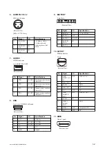
The serial terminal of the battery connector is connected to IC202 on the RE-298 board. This IC202 read the battery
authentication, battery type, remaining power, and other information and send them to the system controller via I
2
C bus
communication.
Power supply voltage detection
The power supply voltage at the DC IN connector is measured by the A/D port on IC202 on the RE-298 board, and it
is posted to the system controller as the input voltage value.
Power system control
IC202 on the RE-298 board checks that the power switch on the unit is turned ON, and turns on the system controller
of IC2101 (DPR-343 board). After that, it controls the power for each circuit block according to the system controller.
The system controller controls the respective power supply systems in the RE-299 and RE-300 boards according to the
operation mode of the device, via the power supply microcomputer (IC202) on the RE-298 board.
1-3-7.
Power Supply System
RE-298/299/300 Boards
The RE-298, RE-299, and RE-300 boards consist of a power circuit (RE-299/RE-300 boards) and a power control unit
(RE-298 board).
However, a part of low-voltage power supply circuit is mounted on the DCP-61 and DPR-343 boards.
Input power supply (UNREG) system operations
An UNREG power voltage is input and is changed to the EVER power voltage state. The power switch ON/OFF state
can be recognized in this mode.
When the power microcomputer (RE-298 board: IC202) recognizes the power switch ON state, the power
microcomputer controls power of each block according to instructions of the system controller (DPR-343 board:
IC2101).
The ordinary input power (UNREG) value is approx. +11 V to +17 V.
• Battery/EXT-DC inputs
These two inputs cannot be physically connected at the same time. Either one power input is selected and supplied.
• Protection of input overvoltage
When a high UNREG power voltage is supplied, the overvoltage protection circuit is activated at the set value of
+19.5 V and the camera body is shut down. This circuit automatically resumes power when the input power voltage
lowers to +19.5 V or less.
• Protection of input low voltage
When a low UNREG power voltage is supplied, the low-voltage protection circuit is activated at the set value of
+10.5 V by the power microcomputer control and the camera body is shut down.
Once the low-voltage protection circuit is activated, the state is maintained. In that case, therefore, turn off the
power switch and replace the battery pack with a charged battery pack or take other appropriate actions.
• UNREG overcurrent detection
An overcurrent detection circuit consisting of IC100 is provided on the RE-299 board. The set value is approx. 4.3
A. Once overcurrent is detected, the circuit is not automatically reset even after the overcurrent is cleared, and
power must be turned on again.
PMW-160/PMW-150/PMW-EX260
1-10
Содержание XDCAM PMW-160
Страница 1: ...SOLID STATE MEMORY CAMCORDER PMW 160 PMW 150 PMW EX260 SERVICE MANUAL 1st Edition ...
Страница 4: ......
Страница 8: ......
Страница 10: ......
Страница 30: ......
Страница 38: ...3 Install the removed parts by reversing steps of removal PMW 160 PMW 150 PMW EX260 2 8 ...
Страница 92: ......
Страница 128: ......
Страница 130: ......
Страница 131: ......

