


1-3-2.
Camera Block System
DCP-61 Board
The camera block consists of a camera signal processor IC that processes the digital camera signal and a camera
microcomputer that controls the camera signal processor IC, CMOS image sensor, and lens. This block outputs the
digital video signal (Y/C) to the following video signal system (baseband).
Digital video signals that are output in the LVDS format from the BI-286 board and the BI-293 board that contain a
CMOS image sensor are sent to the correction IC HELIOS (IC500) on the DCP-61 board. FD white-point detection
correction, clamp processing, monitor frame adjustment, and PI conversion are added to the digital video signals, and
the processed digital video signals are then input to the camera signal processor IC RISE (IC200). The camera signal
processor IC detects values (including video signal average values and peak values) required for camera operations such
as white balance, black balance, focus, iris, and knee processing. Detected values are sent to the camera microcomputer
SUN (IC702).
The digital video signal enters first the selector circuit that selects digital video signal or the test signal, and is then
transferred to the CMOS image sensor correction circuit and the lens correction circuit.
After that, the digital video signal receives white balance processing, flare correction, and then the matrix signal and
the detail signal are added to the video signal. The video signal then receives pedestal control, knee correction, gamma
correction, and white/black clip processing. The video signal is finally output to the baseband processing IC T-ONE
(IC900) .
The processing for converting the number of pixels from 1920/1080 to 1440/1080 or from 1920/1080 to 1280/720 is
also performed in the camera signal processor IC RISE (IC200).
The camera microcomputer SUN (IC702) performs the overall camera control, and is controlled by the system
microcomputer MELON (IC2101) on the DPR-343 board. SUN's peripheral ICs FLASH ROM (IC701) and SDRAM
(IC700) are mounted on the DCP-61 board.
1-3-3.
Video Signal System
DCP-61 Board
The digital video signal (Y/C) sent from the camera signal processor IC RISE (IC200) on the DCP-61 board is input to
the baseband processing IC T-ONE (IC900).
The baseband processing IC T-ONE that incorporates scaler functions (supporting multi-format output), OSD, PLL (54
to 74 MHz), and CPU performs baseband processing for video and audio signals.
The baseband signal processed by T-ONE is sent to the router IC ANDV (IC1700), and is then distributed to inputs and
outputs.The following table lists inputs and outputs of the baseband processing IC T-ONE.
Signal name and input/output
• HD/SD digital component signal
Output to the router IC (Used for outputting SDI/HDMI/VIDEO OUT (without characters))
• HD/SD analog component signal
Output through the A/D converter (IC805) to the router IC (Used for outputting SDI/HDMI/VIDEO OUT (with
characters))
• Analog composite signal
Output to the IO-255 board
• Video signal for LCD
Output through the KSW-62 board to the LCD
• Video signal for viewfinder
Output through the IF-1182 board to the DR-670 board
• Video signal for CODEC
Output through the router IC to the CODEC (IC500, 700: TORINO) on the DPR-343 board
PMW-160/PMW-150/PMW-EX260
1-6
Содержание XDCAM PMW-160
Страница 1: ...SOLID STATE MEMORY CAMCORDER PMW 160 PMW 150 PMW EX260 SERVICE MANUAL 1st Edition ...
Страница 4: ......
Страница 8: ......
Страница 10: ......
Страница 30: ......
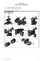
Страница 38: ...3 Install the removed parts by reversing steps of removal PMW 160 PMW 150 PMW EX260 2 8 ...
Страница 92: ......
Страница 128: ......
Страница 130: ......
Страница 131: ......


