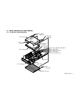
KE-50XBR900(UC)
2-1
SECTION 2
ADJUSTMENTS
1
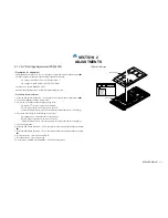
2-1. VS, VD Voltage Adjustment (PDM-5000)
• Preparation for adjustment
1.Slide the DIP switch (S3201) No. 8 of P board to on position with no silkscreen mark
r
.
2.Connect a digital voltmeter to the following terminals of G board.
VS voltage=G board TP1701 (VS)-TP1502 (GND)
VD voltage=G board TP1501 (VD)-TP1502 (GND)
3.Connect a AC cord in DISPLAY UNIT.
4.Perform the adjustment in 10 seconds after connecting the cord.
• Procedure for adjustment
1. Slide the DIP switch (S3201) No. 7 of P board to on position with no silkscreen mark
r
.
2. Confirm the lighting of SONY LOGO LED.
3. Adjust the VS voltage to the following voltage value.
VS voltage of proper value for each model.
Ex.) VS proper value=185V thru 185.6V at 185V.
(Check the proper value with a seal on upper left of panel unit. Refer to right Fig.)
4. Adjust the VD voltage to the following voltage value.
VD voltage ±0.3V of proper value for each model.
Ex.) VD proper value=64.7V thru 65.3V at 65.0V.
(Check the proper value with a seal on upper left of panel unit. Refer to right Fig.)
5. Check a Fan rotation.
6. Slide the DIP Switch (S3201) No. 7 of P board to the off position with the silkscreen mark
r
.
7. Slide the DIP Switch (S3201) No. 8 of P board to the off position with the silkscreen mark
r
.
8. Disconnect an AC cord of DISPLAY UNIT.
9. Reconnect the AC cord in one second.
10. Assure that “POWER ON/STANDBY” LEDs is flashing amber.
+6V
–0V
<SEAL POSITION>
Rear cover assy
SERIAL No.
301201440
Vd=65V
Vs=193.4V
CODE AA-01
BAR CODE SEAL
Panel unit
Содержание WEGA KE-50XBR900, KE-42XBR900
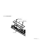
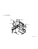
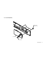
Страница 11: ...KE 50XBR900 UC 1 2 1 1 2 K AND F BOARDS REMOVAL 3 Four screws PSW 3X8 1 Two screws PSW 3X8 2 F Board 4 K Board ...
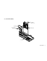
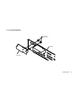
Страница 17: ...KE 50XBR900 UC 1 8 1 2 2 H1 BOARD REMOVAL 1 Two screws BVTP 3X12 2 H1 Board 1 Two screws BVTP 3X12 Front panel ...
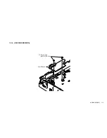
Страница 18: ...KE 50XBR900 UC 1 9 1 2 3 H4 BOARD REMOVAL 1 Two screws BVTP 3X12 2 H4 Board Front panel ...
Страница 19: ...KE 50XBR900 UC 1 10 1 2 4 H3 BOARD REMOVAL 1 Three screws BVTP 3X12 2 H3 Board Front panel ...
Страница 21: ...KE 50XBR900 UC 1 12 1 2 6 H2 BOARD REMOVAL 1 Two screws M 3X8 P SW 2 H2 Board ...
Страница 23: ...KE 50XBR900 UC 1 14 1 2 8 B BLOCK ASSY REMOVAL 1 B Block assy ...
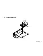
Страница 24: ...KE 50XBR900 UC 1 15 1 2 9 M AD AND AU BOARDS REMOVAL 2 Shield case 1 Screw PSW 3x8 ...
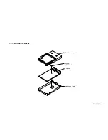
Страница 26: ...KE 50XBR900 UC 1 17 1 2 11 M BOARD REMOVAL 2 Screw PSW 3x8 3 M Board 1 Shield case upper Shield case main ...
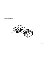
Страница 27: ...KE 50XBR900 UC 1 18 1 2 12 IF BOARD REMOVAL 1 IF Shield sheet 3 IF Board B Block assy 2 Screw PSW 3x8 ...
Страница 28: ...KE 50XBR900 UC 1 19 1 2 13 U1 BOARD REMOVAL 1 Four screws BVTP 3x12 2 U1 Board 3 Core FPC ...
Страница 29: ...KE 50XBR900 UC 1 20 1 2 14 U2 BOARD REMOVAL 1 Tow screws BVTP 3x12 2 U2 Board Rear panel ...
Страница 75: ...KE 50XBR900 UC 4 40 AD AV SW COMPONENT I F DVI AD BOARD COMPONENT SIDE CONDUCTOR SIDE 1 2 A B C D 1 2 A B C D ...
Страница 203: ...KE 50XBR900 UC 202 Sony EMCS Corporation Ichinomiya TEC 9 978 756 02 English 2003BL08 Data Made in Japan 2003 2 ...

