background image

Features

8

Chapt

er

 1

  Ov
er

vie

w

The SR-R1 is a portable memory recorder of the 
SRMASTER series that has 1.5G SDI Dual Link 
/ 3G Dual Link input and output and uses the 
newly developed SRMemory card for recording 
media.

High Quality Recording

Support for SR-SQ (440 Mbps), SR-Lite 
(220 Mbps, and SR-HQ 10/12-bit (880 Mbps)) is 
provided as standard.
There is 16-channel (uncompressed, 24-bit, 
48 kHz) support for audio.

RGB 4:4:4/60p/3D Creation

The SR-R1 is equipped with 1.5G SDI Dual Link 
/ 3G Dual Link and includes recording 
capabilities such as RGB 4:4:4, 50P/59P, and 3D 
to enable support for various scenes.

HD SDI Remote

Support is provided for the HD SDI Remote 
function that is incorporated in many Sony 
camcorders, so recording can be linked to Rec/
Stop on the camera side.

HD CAM camcorder dockable operation

The SR-R1 supports dockable operation with the 
HD CAM camcorder HDW-F900R/650/
PMW-TD300 equipped with HD SDI output, 
using the Docking Plate SRK-R302 (sold 
separately).

Use as PMW-F3 storage

The SR-R1 can be used as high-quality online 
storage for the Digital Cinema Recorder 
PMW-F3. Simultaneous recording and 
synchronized recording (DURATION, 
FILENAME) on the SxS memory card in the 
PMW-F3 and the SRMemory card is possible.

SRExpress

Use SRExpress mode when you want to connect 
to an AJA Video Systems Io XT, KONA 3G, or 
other device that is equipped with a 3G-SDI 
interface and perform high-speed transfer of file 
data.
A 60-minute SR-Lite file can be transferred as an 
MXF file in 15 minutes or less.

SR Motion

The SR Motion function is incorporated as 
standard, which when combined with the 
PMW-F3 enables recordings with slow and quick 
motion effects while maintaining high image 
quality.

422 59ix2 and 50ix2 recording

When used with a HDC2500 camera, the SR-R1 
can record in 422 59ix2 or 50ix2. (double-speed 
recording function for slow motion)

Chapter 

1

Overview

Features

SRMASTER and SRMemory are trademarks of 
Sony Corporation. 
Other system names, products names and 
company names appearing in this manual are 
trademarks or registered trademarks of their 
respective holders. In this manual such names are 
not indicated by ® or ™ symbols.

Содержание SRR1

Страница 1: ...SR R1 SY 4 400 203 06 1 Sony Corporation Printed on recycled paper Printed in Japan 2013 1 32 2011 PORTABLE MEMORY RECORDER SR R1 OPERATION MANUAL English 1st Edition Revised 5 ...

Страница 2: ...try to correct the interference by one or more of the following measures Reorient or relocate the receiving antenna Increase the separation between the equipment and receiver Connect the equipment into an outlet on a circuit different from that to which the receiver is connected Consult the dealer or an experienced radio TV technician for help You are cautioned that any changes or modifications no...

Страница 3: ...sques d incendie ou d électrocution ne pas exposer cet appareil à la pluie ou à l humidité Afin d écarter tout risque d électrocution garder le coffret fermé Ne confier l entretien de l appareil qu à un personnel qualifié Ne pas installer l appareil dans un endroit confiné par exemple une bibliothèque ou un placard encastré IMPORTANT La plaque signalétique se situe sous l appareil AVERTISSEMENT Un...

Страница 4: ...uments Service SAV ou Garantie Bitte lesen Sie dieses Handbuch vor der Benutzung des Geräts sorgfältig durch und bewahren Sie es zum späteren Nachschlagen auf Um die Gefahr von Bränden oder elektrischen Schlägen zu verringern darf dieses Gerät nicht Regen oder Feuchtigkeit ausgesetzt werden Um einen elektrischen Schlag zu vermeiden darf das Gehäuse nicht geöffnet werden Überlassen Sie Wartungsarbe...

Страница 5: ...Für Kunden in Europa Dieses Produkt wurde von oder für Sony Corporation 1 7 1 Konan Minato ku Tokio 108 0075 Japan hergestellt Bei Fragen zur Produktkonformität auf Grundlage der Gesetzgebung der Europäischen Union kontaktieren Sie bitte den Bevollmächtigten Sony Deutschland GmbH Hedelfinger Strasse 61 70327 Stuttgart Deutschland Für Kundendienst oder Garantieangelegenheiten wenden Sie sich bitte ...

Страница 6: ... for Selecting a Menu 26 Locking the Controls 27 Signal Format Settings 28 Selecting the Signal Format 28 Display Settings 29 Using the Backlight 29 Using the Screen Saver 29 Date Settings 29 Chapter 4 Recording and Playback Recording Preparations and Operations 30 Setting the Audio Signals 30 Setting the Recording Levels 31 Setting the Time Code and User Bits 32 Recording 35 Playback Preparations...

Страница 7: ...Video 78 Audio 78 Input Output Connectors 78 Supplied Accessories 79 Optional Accessories 79 Error Messages and Warning Messages 80 About Error Messages 80 About Warning Messages 81 Warning System 84 Troubleshooting 86 About Recording Playback Formats 90 Monitor LUT Function 92 Connection to the PMW F3 96 Synchronized Recording 96 Synchronizing File Names 97 Monitor LUT 97 Select FPS Recording 98 ...

Страница 8: ...y Use as PMW F3 storage The SR R1 can be used as high quality online storage for the Digital Cinema Recorder PMW F3 Simultaneous recording and synchronized recording DURATION FILENAME on the SxS memory card in the PMW F3 and the SRMemory card is possible SRExpress Use SRExpress mode when you want to connect to an AJA Video Systems Io XT KONA 3G or other device that is equipped with a 3G SDI interf...

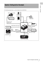
Страница 9: ...00M 00S 00F EE 16 5V A001C001_120530RT SDI EMP 2 L R SDI EMP 3 L R SDI EMP 4 L R SDI EMP 5 L R SDI EMP 6 L R SDI EMP 7 L R SDI EMP 8 L R SDI EMP 9 L R SDI EMP 10 L R SDI EMP 11 L R SDI EMP 12 L R SDI EMP 13 L R SDI EMP 14 L R SDI EMP 15 L R SDI EMP 16 L R MK HD color video camera HD VTR etc Earphones Headphones Microphone VTR etc HD SDI video audio input HD SDI video audio output REMOTE cable incl...

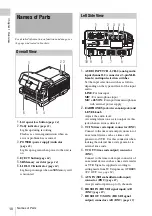
Страница 10: ...IC 48V ON For input from microphones with external power supply 2 EARPHONES jack stereo mini jack and LEVEL knob Adjusts the audio level A warning alarm tone is also output via this jack when an error is detected 3 TC IN time code input connector BNC Connect to the time code output connector of an external device such as a time code generator or VTR Use this connector when locking the internal tim...

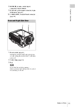
Страница 11: ...0 CTRL PANEL Control Panel connector page 16 1 Power switch page 23 Setting the switch to the side turns power on and setting the switch to the 1 side turns power off 2 Cable clamp page 16 3 Fan Note Do not block the ventilation openings Otherwise internal heat buildup can lead to a risk of fire and damage to the unit Rear and Right Side View 1 3 2 ...

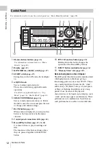
Страница 12: ...is button changes the operation of the Record Play buttons 11 EJECT button and indicator page 24 12 Memory Stick slot page 101 Note on faulty pixels on the LCD panel The LCD panel fitted to this unit is manufactured with high precision technology giving a functioning pixel ratio of at least 99 99 Thus a very small proportion of pixels maybe stuck either always off black always on red green or blue...

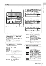
Страница 13: ...8PsF 4 2 2 ENCODE SR SQ 10bit 60min LOCAL 16 6V 00H 00M 00S 00F A001C001_120530RT MK 60min LOCAL 16 6V 1 2 4 10 3 5 6 7 8 9 11 11 SDI IN 1 5G SINGLE LINK SDI OUT 1 5G SINGLE LINK MK 00 00 00 01 00H 00M 00S 00F A001C001_120530RT MK 60min LOCAL 16 6V 11 Sections 6 to 9 change to the condition shown as 11 below when the HOME button is pressed while holding down the FUNC button TCR TCG UBR UBG TM1 TM2...

Страница 14: ...For details on this setting see MODE COLOR page 73 11 Signal format file information indication page 28 When the FUNC and HOME buttons are pressed simultaneously from top to bottom the system and the encoding are displayed the playback output of the playback file the recording date and time and the duration are displayed or the MARK IN point and the SDI input output format are displayed To switch ...

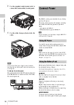
Страница 15: ...tach the supplied CP bracket to the unit and connect the unit and the control panel with the control panel cable 1 Attach the supplied CP bracket to the right side of the unit 2 Slide the control panel into the CP bracket Chapter 2 Preparation Work Flow Mount control panel page 15 Connect power page 16 Connect HD SDI compliant equipment page 19 Turn power on page 23 Insert SRMemory card page 24 Mo...

Страница 16: ...s required Use the DC power cable sold separately to connect the AC adapter AC DN10 to the DC IN connector on the SR R1 Note When connecting the output of a battery to the DC IN connector access the SYSTEM Setup menu and set the BATTERY DC IN TYPE option to other than AC Adapter see page 75 Before using the battery pack charge it fully with the dedicated battery charger For detailed information on...

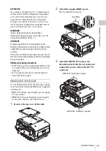
Страница 17: ...e entsorgen müssen Sie die Gesetze der jeweiligen Region und des jeweiligen Landes befolgen Battery pack usage precautions If the battery pack is charged immediately after use while still warm a full charge may not be achieved If not using the unit for an extended period detach the battery pack Attaching the battery pack To attach the battery pack the following options must be installed using the ...

Страница 18: ...e battery pack is attached incorrectly the connectors may be damaged Removing the battery pack While power to the unit is switched off hold down the lock release button and push the battery pack off Notes Never remove the battery pack while a recording is in progress tally indicator is lit in red Always turn power to the unit off before removing the battery pack 1Battery pack 2 Main unit battery p...

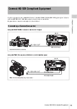
Страница 19: ...nector A B of the SR R1 Representative connection examples are shown below Using the HDW F900R or similar to record a 4 2 2 signal Using the PMW F3 to record an RGB 4 4 4 or 4 2 2 50p 59p signal Connect HD SDI Compliant Equipment Connecting a Camera Camcorder HD SDI OUT HD SDI IN A HDW F900R HD Camcorder SR R1 HD SDI A B OUT HD SDI IN A HD SDI IN B PMW F3 Solid State Memory Camcorder SR R1 ...

Страница 20: ...al Using two HD cameras e g HDC2000 series to record HD SDI OUT L HD SDI OUT R HD SDI IN A HD SDI IN B PMW TD300 Solid State Memory 3D Camcorder SR R1 SDI 1 SDI 2 HD SDI IN A HD SDI IN B HDC2500 HD Color Camera SR R1 SDI 1 2 SDI 1 2 HD SDI IN A HD SDI IN B GENLOCK HDC2000 Series HD Color Camera SR R1 TEST OUT HD SYNC Note Synchronize the two cameras ...

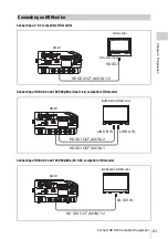
Страница 21: ...080 50p 60p Dual Link compatible HD monitor Connecting a RGB4 4 4 and 1080 50p 60p 3G SDI compatible HD monitor Connecting an HD Monitor HD SDI OUT MON 1 2 HD SDI HD monitor HD video input SR R1 HD SDI OUT MON 2 LINK B IN LINK A IN HD SDI OUT MON 1 BVM E250 HD Monitor SR R1 3G SDI IN HD SDI OUT MON 1 2 BVM L230 HD Monitor SR R1 ...

Страница 22: ...h synchronized camera switcher signal generator etc Tips If no external synchronization source is available internal sync will be used When inputting signals from two cameras simultaneously the cameras must be synchronized via GENLOCK for example About the Reference Sync Signal HD SDI IN A B HD SDI OUT REF IN GENLOCK IN SR R1 Reference signal LINK A only or LINK A B Camera switcher signal generato...

Страница 23: ...sed on the actual connection condition but on the setting made under SYSTEM Setup BATTERY DCIN TYPE see page 75 Set DCIN TYPE to match the power supply being used Tips When signal format and SR Motion are shown the indication appears at bottom right The voltage shown is the actual voltage used by the unit this may be lower than the input voltage and the DC IN connector When a battery pack is selec...

Страница 24: ...ay This indicates that the previous recording did not complete normally For information on what to do in this case see Salvaging SRMemory cards for which recording did not complete properly page 86 in the Troubleshooting section To remove the SRMemory card 1 Press the EJECT button on the control panel while power on the unit is on or set the power switch on the unit to the off position The files i...

Страница 25: ...use a newly purchased SRMemory card right away To format an SRMemory card on which data were recorded proceed as follows Note Formatting will erase all files and data on the SRMemory card For details on menu operation see Basic Menu Operations page 26 1 Press the SYSTEM button The SYSTEM Setup menu appears 2 Select and confirm SRMemory t select and confirm FORMAT t move the cursor to OK and confir...

Страница 26: ...s a command the command is executed Chapter 3 Basic Menu Operations Menu Overview TC Setup Serves for making time code settings VIDEO Setup Serves for making video output settings AUDIO Setup Serves for making audio signal related settings SYSTEM Setup Serves for making system settings Buttons Used for Menu Operations HOME TC VIDEO AUDIO SYSTEM EJECT STOP PLAY KEY INHI BACK OFF ON LIGHT OFF ON REC...

Страница 27: ...p menu is set to Map the KEYMAP settings apply see page 74 TCG Setting Main DF NDF UBG SRC 12H 24H DF TCG 24H T C S e t u p TIMER SEL TIMER RESET TIMER PRESET TCR SEL TCG MODE REGEN SRC RUN MODE TCG SET OTHERS CHAR LTC TC PRST INT L R RUN SR R1 TCR 00 00 00 00 STOP Submenu window 24H 12H 12H 24H MODE TCG Setting Main DF NDF UBG SRC 12H 24H DF TCG 24H T C S e t u p TIMER SEL TIMER RESET TIMER PRESE...

Страница 28: ...ange the values for such items The settings complete message is shown and the HOME screen appears again Signal Format Settings Selecting the Signal Format Resolution S Y S T E M S e t u p SR R1 TCR 00 00 00 00 STOP System Format FRAME TC SIGNAL SELECT FPS 29 97 422 OFF FILE LIST SYSTEM FORMAT INGEST PB FUNCTION TEST SG LCD KEY MAP KEY INHI MAP REMOTE LOCAL LCL REC INHI OFF POWER BATTERY SRMemory O...

Страница 29: ...select Disable Default setting Disable Display the System menu and select OTHERS SET DATE menu to set the date and time of the unit To set the date and time OTHERS SET DATE menu 1 Display the System menu and then select and confirm OTHERS t select and confirm SET DATE 2 Set the year month day local time and UTC Coordinated Universal Time offset e g 9 00 for Japan and then select and confirm SET No...

Страница 30: ...o record SIGNAL FORMAT in the SYSTEM Setup menu page 28 Select the audio signals to record INPUT SEL in the AUDIO Setup menu page 30 Set the audio signals to monitor PHONE SEL in the AUDIO Setup menu page 31 Set the display range of the audio level meters METER TYPE in the AUDIO Setup menu page 31 Set the recording levels REC LEVEL in the AUDIO Setup menu page 32 Adjust the levels of audio signals...

Страница 31: ...nals Display the AUDIO Setup menu and then 1 select and confirm MIX MODE t2 select and confirm the mixing mode ADD Simple addition RMS Geometric mean Average Simple average Use the AUDIO Setup menu to make settings related to the recording levels Press the AUDIO button to display the AUDIO Setup menu The recording levels can be checked with the audio level meters displayed in the display on the co...

Страница 32: ...of each of the other channels in the same way 5 When you have finished making the settings move the cursor to and confirm END Use the TC Setup menu to make settings related to audio signals Press the TC button to display the TC Setup menu To select the time data to display Display the TC Setup menu and then 1 select and confirm TIMER SEL t2 select and confirm the time data you want to display TC D...

Страница 33: ...an be set to an arbitrary value in the menu RGN EXT L In accordance with the time code input via the TC IN connector SDI L In accordance with the LTC time code of the video signal input via the HD SDI IN A B connector SDI V In accordance with the VITC time code of the video signal input via the HD SDI IN A B connector Menu item User bits TCG SET UBG SOURCE TCG MODE TCG PRST Arbitrary user bits can...

Страница 34: ...d then set TCG MODE to RGN and select the signal for the time code generator to regenerate in REGENE SOURCE For details see To select the time code to record page 33 Note External synchronization is not possible in Select FPS format During Select FPS set TCG MODE to PRST To synchronize the time codes of two SR R1 units As an alternative to connecting a time code generator to the TC IN connectors o...

Страница 35: ...Y button while holding down the REC button Recording starts and REC LOCK appears 3 Press the STOP button to stop recording The AUDIO Setup menu allows you to make various settings related to audio monitor signals for playback The setting procedures are the same as for recording For details see Setting the Audio Signals page 30 and AUDIO Setup Menu page 67 To adjust the level of audio output via th...

Страница 36: ... list The SEAMLESS setting is disabled during Select FPS format Performs variable speed playback according to the speed at which the ADJUST knob is turned 1 Press the PAUSE button in the HOME screen during playback to enter the PLAY PAUSE state You can also perform this during shuttle playback 2 Turn the ADJUST knob Jog playback is performed according to the speed at which the knob is turned Perfo...

Страница 37: ... By pressing the STOP button during the STBY OFF state you can perform mounting again and enter the STOP state The lid lock function will be released in Standby Off mode as less power is consumed in this mode If you eject an SRMemory card in the REC PAUSE or STBY OFF state the unit will switch to the STOP state Note As starting recording or playback from Standby Off mode requires a mounting operat...

Страница 38: ...e unit enters Standby Off mode PLAY button and indicator Starts playback The indicator is lit during playback To start recording press this button while holding down the REC button The indicator blinks if the recording and playback operations are not locked The immediately preceding recording plays and enters the REC PAUSE state REC REVIEW REC button and indicator To start recording press the PLAY...

Страница 39: ...rder of x2 t x5 t x8 t x16 t x32 t x2 If this button is pressed after a search is interrupted by another operation a search is performed at the last speed used during the previous search F FWD button and indicator NEXT Moves to the beginning of the next file If this button is pressed during the STOP state moves to the last frame of the LAST REC FILE Move operations are disabled when POWER MODE is ...

Страница 40: ...e f VITC field mark blank When odd field displayed When even field displayed g Battery voltage Indicates the voltage of the battery or AC power supply h File name Indicates the name of the file that will be recorded next or the name of the currently playing file To display warning error messages 1 Set CHAR MODE in the TC Setup menu to other than TIME 2 Set WARN to W E to display both warning messa...

Страница 41: ...u can set a MARK IN point using the control panel during recording or playback Tips A MARK IN point is active until the SRMemory card is removed or until an IN point is entered Up to three MARK IN points can be set in each file If you set additional points the previous points will be discarded starting with the oldest To set a MARK IN point While the HOME screen is displayed on the control panel d...

Страница 42: ... the entered time code exist in the file or a corresponding point does not exist cuing will fail An IN point is active until the SRMemory card is removed or until MARK IN points are set To enter an IN point Enter the time code in IN POINT under PB FUNCTION of the SYSTEM Setup menu Information on the IN point is displayed in the time data indication of the HOME screen as follows If a valid IN point...

Страница 43: ...ms Displays the items displayed in the file list You can turn the SELECT ENTER dial while holding down the FUNC button to change the display items FILE LIST Operations Displaying a File List File List FILE LIST SORT Data S Y S T E M S e t u p SR R1 TCR 00 00 00 00 STOP FILE LIST SYSTEM FORMAT INGEST PB FUNCTION TEST SG LCD KEY MAP KEY INHI MAP REMOTE LOCAL LCL REC INHI OFF POWER BATTERY SRMemory O...

Страница 44: ...KP keep t none Files can be renamed and deleted 1 Select a file and then press the SELECT ENTER dial while holding down the FUNC button to confirm the selection t2 select and confirm the desired operation RENAME Renames the file DELETE Deletes the file PROTECT Changes the file protection setting ALL DEL Deletes all files To rename a file Select and confirm RENAME to display the file rename screen ...

Страница 45: ...the system according to the file playback format To properly play back files that cannot be played in the current system format i e files displayed in gray or files for which the converted playback icon appear the system settings must be changed according to the files You can quickly change the system settings as follows 1 Select the file and press the SELECT ENTER dial while holding down the STOP...

Страница 46: ...1 Turn the ADJUST knob to select the corresponding file 2 Turn the SELECT ENTER dial to select the MARK IN point and press the SELECT ENTER dial to confirm The MARK IN point opens To delete MARK IN points 1 Turn the ADJUST knob to select the corresponding file 2 Turn the SELECT ENTER dial to select the MARK IN point and press the SELECT ENTER dial while holding down the FUNC button 3 Select and co...

Страница 47: ...firm t 3 select and confirm SET The system reboots automatically and starts in SRExpress mode During SRExpress mode This unit is controlled remotely via RS 422 interface Recording and playback operations cannot be performed from the control panel SRExpress mode appears in the HOME screen and information such as the time code and audio level is not displayed INGEST Mode SRExpress Mode MXF MXF Thund...

Страница 48: ...SDI INGEST appears in the status indication of the HOME screen Recording cannot be performed in SDI INGEST mode Key operations from the control panel are performed according to the KEY MAP setting of the SYSTEM Setup menu Files for which converted playback was performed in normal mode i e items marked with in the file list will be removed from the list of files that can be played i e these files w...

Страница 49: ... number of frames at playback time and target frame frequency You can check review the motion effects immediately after shooting Since only the required number of frames is recorded no format conversion is needed SR Motion has the following functions 1 This is only supported when PMW F3 is connected Notes Audio is not recorded with SR Motion SR Motion cannot synchronize two or more recorders even ...

Страница 50: ...stem frequency of 23 98PsF When video shot and recorded at 60 frames per second FPS is played back at 24 FPS it is played back in slow motion at 24 60 0 4 times normal playback speed If you set the format for recording in accordance with the target frame frequency system frequency at playback the time code can continuously advance during playback Editing or other post processing of the recorded fi...

Страница 51: ...ain quick motion effects shoot with undercranking To obtain slow motion effects shoot with overcranking Example When the target frame frequency is 23 98PsF To obtain quick motion effects Set shooting frames to 23 FPS or less To obtain slow motion effects Set shooting frames to 25 to 60 FPS Setting shooting frames to 60 FPS results in playback in slow motion at 0 4 times normal playback speed Shoot...

Страница 52: ...s and instead advances from the 0 to 23 frames of the target frame frequency If 1 second is recorded with these settings beginning from the 00 second 00 frame the time code advances quickly from the second 00 frames 00 to 23 and then continues to advance as second 01 frames 00 to 23 and finally as second 02 frames 00 to 11 at which point a total of 60 frames have been recorded see the following fi...

Страница 53: ...yback SR Motion Operation Flow Connect the unit to the camera Set the target frame frequency playback time code Select the system format to use during shooting Select the SR Motion mode function Set the number of frames to shoot Shoot Review ...

Страница 54: ...nction that allows you to obtain slow quick motion effects by connecting the unit to the PMW F3 adjusting the number of frames and then shooting The number of frames recorded in 1 second is indicated as FPS frames per second The number of frames can be set in 1 FPS increments within the range of 17 to 60 FPS Target Frame Frequencies and Signal Formats Menu settings Unit state Format FPS FORMAT SEL...

Страница 55: ...mes in which no signal is recorded This unit extracts and stores only effective frames and records them to an SRMemory card When the recorded file is played back at 24P a slow motion effect of 0 48 times normal playback speed is obtained 10 1 2 3 4 5 6 7 8 9 50 48 49 50 FPS NV 1 2 3 4 5 6 NV 7 8 9 10 NV 48 49 50 60P 1 2 3 4 5 6 7 8 9 10 48 49 50 1 2 3 4 22 23 24 Format S59P 23PsF SELECT FPS ON Num...

Страница 56: ...e HOME button while holding down the FUNC button the signal format display at the bottom of the screen changes to the SR Motion display allowing you to check the setting for the number of frames to shoot 4 Start shooting Use the SYNCHRO REC function and use the REC button on the PMW F3 to start stop recording For details on the SYNCHRO REC function see Synchronized Recording page 96 System Format ...

Страница 57: ...created during recording will be named using the following naming system Example D003C004_120325E5 1 Camera ID The camera ID configured in CAMERA ID under FILE LIST of the SYSTEM Setup menu 2 Reel number The reel number configured in REEL NO under FILE LIST of the SYSTEM Setup menu If you change only the camera ID setting the reel number will be changed to 001 3 Shot Number A sequentially assigned...

Страница 58: ... to 001 When a setting other than OFF is specified for OTHERS REC TRIGGER in the SYSTEM Setup menu REC START STOP operations can be controlled externally When REC TRIGGER is set to SDI RMT By connecting the SDI output of an SR R1 F65 or camcorder that supports SDI remote output you can control REC START STOP operations from these devices This setting does not allow playback When REC TRIGGER is set...

Страница 59: ...on is included When REC TRIGGER is not set to OFF SDI REMOTE information that is input to SDI IN is copied Even if the unit can not record SDI REMOTE REC information is included in the SDI OUT signals when SDI REMOTE REC information is input to SDI IN If information from SDI REMOTE IN cannot be received properly a SDI RMT IN NG warning appears and SDI REMOTE information is not included in the SDI ...

Страница 60: ... becomes 00 00 00 00 time code or 00 00 00 00 user bits Notes The values read by the time code reader cannot be reset Time data cannot be reset when the time code generator is locked to external time codes or to values read by the time code reader TIMER PRESET Selects the type of time data to preset to an arbitrary value TCG TC Time code generated by the time code generator TCG UBIT User bits gene...

Страница 61: ...generator settings related to the main time code DF NDF Valid only when the frame frequency of this system is 29 97 Hz Sets the frame count mode DF Drop Frm Drop frame mode NDF Non Drop Frm Non drop frame mode Note This settings is valid only when TCG MODE is set to PRST UBG SOURCE Selects the source time code of user bits TCG TCG Source Same source time code as that of the time code generator INT...

Страница 62: ... RT SET settings Select this under normal circumstances DATE DATE Records the current time of the unit s internal clock i e the time displayed on the control panel and the status indication Continuity for frames is not guaranteed with this method LTC Delay Sets the phase difference between the LTC input from the TC IN connector and the time code generator 0 NO Delay Same timing 1F 1F Delay The gen...

Страница 63: ...Without BG White characters with no background OUTL Outline White characters with black outlines TRNS Translucent White characters on a gray screen background BG With BG White characters on a black background SIZE Sets the size of text information x1 x1 Normal x2 x2 Twice normal size MODE Sets the content of text information STAT Time Status Time counter display information and status operation st...

Страница 64: ...D SDI OUT MON 1 REMAIN Sets whether or not to display the remaining amount of possible recording time estimated from the current recording settings of the SRMemory card OFF Off Does not display ON On Displays BATT Sets whether or not to display the remaining amount of battery power OFF Off Does not display ON On Displays FILENAME Set whether to display the file name OFF Off Does not display ON On ...

Страница 65: ... outputs when SPLIT is selected MON2 OUT Sets the signal output from HD SDI OUT MON connector 2 when the system is set to 3D mode and SDI OUT is set to 1 5G Single LINKA Link A Outputs the Link A signal LINKB Link B Outputs the Link B signal SPLIT Split Outputs in split screen layout The split pattern can be configured using the SPLIT MODE SPLIT H SPLIT V setting Note Metadata will not be included...

Страница 66: ...m LUT conversion BANK0 Bank 0 Selects the LUT file in bank 0 BANK1 to BANK3 Bank 1 to Bank 3 Selects the LUT file in any of bank 1 bank 2 and bank 3 FtH Full to Head Does not use a LUT file and instead adjusts signals that exceed the HD video level range 4 to 1 019a steps to match the standard video levels from 64 0 black to 940a 100 white steps and then displays them a During 10 bit signal level ...

Страница 67: ...me settings as TRACK1 SDI8 TRACK9 Selects the signal to assign to track 9 Same settings as TRACK1 SDI9 TRACK10 Selects the signal to assign to track 10 Same settings as TRACK1 SDI10 TRACK11 Selects the signal to assign to track 11 Same settings as TRACK1 SDI11 TRACK12 Selects the signal to assign to track 12 Same settings as TRACK1 SDI12 TRACK13 Selects the signal to assign to track 13 Same settin...

Страница 68: ... Sets whether or not to add a delay to the HDSDI input audio OFF Off Does not add delay ON On Adds delay ANALOG Sets whether or not to add a delay to the ANALOG input audio OFF Off Does not add delay ON On Adds delay AUX IN Sets whether or not to add a delay to the AUX IN input audio OFF Off Does not add delay ON On Adds delay DELAY Sets the delay length for items set to be delayed 0 NO Delay Does...

Страница 69: ...K NG NG Displays only files that are marked NG KEEP Keep Displays only files that are marked KEEP w o NG without NG Displays only files that are not marked NG Notes This item cannot be changed during file playback When the power is turned off the setting changes to ALL CAMERA ID Sets the camera ID for when saving using CAMERA format file names A to Z Note Depending on the SRMemory card inserted in...

Страница 70: ...3D For details see About Recording Playback Formats page 90 SELECT FPS Selects the operation mode for the Select FPS function OFF Off Disables the Select FPS function ON On Enables the Select FPS function and uses the number of frames FPS configured on the camera For details see SR Motion page 49 FPS FORMAT Selects the system format operation frame frequency during Select FPS operation S25 S25 S29...

Страница 71: ...ode ON On Enables SDI INGEST mode RMT DUB Remote Dub Enables SDI INGEST mode in addition to superimposing the SDI REMOTE signal of the HDCAM onto the SDI OUT signal and sending REC commands during playback that was started via a SYNC PLAY command OFF Off Disables SDI INGEST mode For details on SDI INGEST mode see SDI INGEST Mode page 48 PB FUNCTION IN POINT Specifies time codes for setting the tim...

Страница 72: ...repeat playback OFF Off Disables repeat playback ON On Enables repeat playback Tip The range for repeat playback is determined by the PB CONTINUE setting REC REVIEW Specifies the REC REVIEW playback range for when the PLAY button is pressed while holding down the FUNC button on the control panel ALL All Plays back the last recorded file from beginning to end 5SEC 5sec Plays back the last 5 seconds...

Страница 73: ...s 1min 1min Turns the backlight off after 1 minute 3min 3min Turns the backlight off after 3 minutes 5min 5min Turns the backlight off after 5 minutes BRIGHT Sets the backlight brightness 0 to 31 20 LCD MODE Switches between horizontal and vertical display for the LCD HORIZ Horizontal Horizontal display VERT Vertical Vertical display Tip You can also perform switching by pressing the FUNC BACK HOM...

Страница 74: ...on ALL ALL Locks all MAP MAP Locks only the buttons that are set to Disable in the KEYMAP settings REMOTE LOCAL Selects the operation method of the unit LCL Local Enables the unit to be operated from the control panel In such cases do not connect any external device to the REMOTE IN connector RMT Remote Enables the unit to be operated from an external device connected to the REMOTE IN connector In...

Страница 75: ...nters power saving mode after 30 seconds 1min 1min Enters power saving mode after 1 minute 2min 2min Enters power saving mode after 2 minutes 5min 5min Enters power saving mode after 5 minutes 10min 10min Enters power saving mode after 10 minutes 20min 20min Enters power saving mode after 20 minutes 40min 40min Enters power saving mode after 40 minutes 60min 60min Enters power saving mode after 60...

Страница 76: ...ate Settings page 29 META DATA Sets 3 line metadata input REC TRIGGER Sets the recording start input trigger signal OFF Off Recording is not triggered by an input signal SDI RMT SDI REMOTE Recording is triggered by the HDCAM s SDI REMOTE signal SDI R P SDI RMT Playable Recording is triggered by the HDCAM s SDI REMOTE signal a SYNC SYNCHRO REC Recording is triggered by the PMW F3 SYNC P SYNC REC Pl...

Страница 77: ...keep the unit working properly and to prolong its usable lifetime Contact a Sony service or sales representative for more information about inspections Appendix Maintenance and Inspections Note About the Power Supply Terminal Specifications General Recording format MPEG4 SStP format Power supply 11 to 17 V DC Power consumption 30 W 422 23 98PsF SR Lite recording Operating temperature 0 C to 40 C 3...

Страница 78: ... dB at reference level Dynamic range More than 100 dB 1 kHz Distortion Less than 0 05 1 kHz at reference level Crosstalk Less than 80 dB 1 kHz between any two channels Input Output Connectors Input connectors AUDIO INPUT CH 1 CH 2 3 pin XLR female 2 LINE MIC MIC 48 V TC IN BNC 1 0 5 Vp p to 18 Vp p 10 kΩ SMPTE linear time code compliant AUX IN BNC 1 HD SDI embedded audio 1 485 Gbps SMPTE 292M comp...

Страница 79: ...512 GB SR 1TS25 1TS55 1 TB Notes Always make a test recording and verify that it was recorded successfully SONY WILL NOT BE LIABLE FOR DAMAGES OF ANY KIND INCLUDING BUT NOT LIMITED TO COMPENSATION OR REIMBURSEMENT ON ACCOUNT OF FAILURE OF THIS UNIT OR ITS RECORDING MEDIA EXTERNAL STORAGE SYSTEMS OR ANY OTHER MEDIA OR STORAGE SYSTEMS TO RECORD CONTENT OF ANY TYPE Always verify that the unit is oper...

Страница 80: ...SDI EMP 12 L R SDI EMP 13 L R SDI EMP 14 L R SDI EMP 15 L R SDI EMP 16 L R LOCAL EE 21 46 REMAIN 10min PLAY LOCK LTC INTRP DF EXT LK VTR OOOOO 16 5V STANDARD ENCODE TCG RECINHI KEYINHI 00H 00M 00S 00F A001C001_120530RT MK 59 94I 1920x1080 4 2 2 ERROR E010 E010 FAN STOP FAN STOP FAN Stopped 1 Error s 2 Warning s Popup window displaying error message E010 FAN STOP fan stopped Indicates that there is...

Страница 81: ...E058 AV WRITE ERROR Detected an audio video recording error due to interface or memory problem E059 AV READ ERROR Detected an audio video playback error due to interface or memory problem E05A WRITE FAIL OW Detected an access error when recording an AV file to the SRMemory card Proper recording is not possible The power may have been turned off before unmounting of the card was complete E05B CANNO...

Страница 82: ...tion slot lid is open W014 VPID FERQ MISMAT The VPID frequency information does not match that of the system W015 VPID C SP The color space information in the video payload identifier VPID of the input signal and the SYSTEM settings 444 422 do not match W016 VPID LINK The LINKA B information in the video payload identifier VPID of the input signal and the connectors used do not match W017 MEDIA RE...

Страница 83: ...UX IN is selected in the AUDIO menu but the input signal of the AUX IN connector and the video signal input to the unit is not locked W03C HD SDI OUT NG 3G SDI OUT is not being output properly W03D ENCODER NG Encoder initialization failed W03E ENC WARNING Recording malfunction encoder error W03F DEC WARNING Cannot playback data from SRMemory card decoder error W050 WP SW ON The SRMemory card write...

Страница 84: ...lock lost during recording below Operation continues Check the warning message and resolve the condition a b Servo lock lost during recording Recording continues but results may invalid Check the input signal An error occurred Operation continues or stops depending on the type of error Check the error message and resolve the condition Alternatively contact a Sony service representative a SRMemory ...

Страница 85: ...ounting in progress The power cannot be turned off Do not turn off the power switch until the processing is complete a Output only during recording b Flashes during recording c You can use the battery level external power indication on the display to check the state of the battery see page 14 23 Warning tones 1 beeps second 4 beeps second Continuous tone Alarm tones 1 beeps second 4 beeps second C...

Страница 86: ... insert an SRMemory card that requires salvaging or turn on the unit with such a card inserted a popup message asking whether you want to perform salvaging will appear Recording and playback are disabled for SRMemory cards that require salvaging When you format an SRMemory card the memory card will be ready for use immediately However any previously recorded data will be lost To restore files via ...

Страница 87: ... 4 2 2 mode a 4 4 4 picture is input Input a 4 2 2 format signal Picture break up The input signal is unstable Supply a correct input signal The monitor does not support the format Some older monitors support only the 59 94 60 frequencies The input signal is not matched to the system frequency Input a signal with 1 000 1 000 and 1 000 1 001 that match the system The frequency exceeds the monitor s...

Страница 88: ...put the correct HD SDI signal No analog audio input Electret condenser microphone is not powered Change the setting to 48 V ON except for internal battery powered microphone Want to output a test signal This can be done with a menu setting Set SYSTEM TEST SG AUDIO to 1kHz Test signal is not output Test signals are turned off when the unit is powered off and on Select the test signal again Problem ...

Страница 89: ...e is too long causing a voltage drop If the power cable is too long or does not have a sufficient current capacity rating cable impedance can cause a voltage drop Replace the cable with a shorter one Battery alarms appear frequently If battery alarms appear even when the input voltage is sufficient the END and NEAR END settings for the DC power supply are wrong Change the END and NEAR END settings...

Страница 90: ...0 422 10 bit S25PsF 25PsF a a S29PsF 23PsF 29PsF a a S50PsF 25PsF a a S59PsF 23PsF 29PsF a a Select FPS setting Number of lines Signal FPS Format system frame frequency Frame TC target frame frequency Encoding SR HQ SR SQ ON 1920 1080 444 10 bit S25PsF 25PsF a a S29PsF 23PsF 29PsF a a Select FPS setting Number of lines Signal Frame TC target frame frequency Encoding SR SQ SR Lite OFF 1920 1080 422...

Страница 91: ...tting Number of lines Signal Frame TC target frame frequency Encoding SR HQ SR SQ OFF 1920 1080 444 10 bit 50i a 59i a 23 98PsF a a 24PsF a a 25PsF a a 29 97PsF a a 444 12 bit 23 98PsF a 24PsF a 25PsF a 29 97PsF a 444 3D 10 bit 50i a 59i a 23 98PsF a a 24PsF a a 25PsF a a 29 97PsF a a ...

Страница 92: ...ile format page 95 Use the CvpFileEditor 1 software to create LUT files The latest version of CvpFileEditor can be downloaded from the Sony professional products software download site eCSite 1 CvpFileEditor is a trademark of Sony Corporation To load a LUT file into a bank Proceed as follows to load a LUT file from a Memory Stick into one of the banks of this unit 1 Insert a Memory Stick containin...

Страница 93: ...l to select the bank that contains the LUT file that you want to delete and then press the dial with the FUNC button held down The bank with the file that you want to delete is selected displayed in yellow 2 Press the SELECT ENTER dial with the FUNC button held down You can delete all of the LUT files in all banks at once For the procedure see To delete all LUT files from all banks page 94 BANK0 7...

Страница 94: ...DEO Setup menu select LUT LUT MODE A setup window opens 2 Select the bank of the LUT file that you want to save 3 Insert a Memory Stick with the folder MSSONY PRO SRMASTER R1 LUT into the Memory Stick slot 4 In the VIDEO Setup menu select LUT LUT SAVE 5 Rotate the SELECT ENTER dial to select OK and then press the dial with the FUNC button held down To delete all LUT files from all banks 1 In the V...

Страница 95: ... data If a LUT file containing 16 bit data is loaded the most significant 16 bits of each data item are simply bit shifted and treated as 12 bit data Data Enter 4096 output values for 1024 input values in ascending order of input values Each value must be on its own line 112 First data item output value for input value 0 116 Second data item output value for input value 1 116 Third data item outpu...

Страница 96: ...pears at the bottom right of the HOME screen Recording start stop operations performed on the PMW F3 in this mode will affect both the PMW F3 and the SR R1 simultaneously Connection to the PMW F3 Off line File On line File HD video monitor PMW F3 SRMemory S Log monitoring LUT baked in SR R1 SR Lite SR SQ Monitor LUT SxS Memory Card MPEG 2 35 Mbps 4 2 0 8 bit LUT baked in Online editing Offline edi...

Страница 97: ...e name indication of the HOME screen When the input data includes file name information the beginning of the file name indication will appear Note Certain characters cannot be used in the file name Files names cannot be synchronized if the file names configured on the PMW F3 contain the following If a file name contains any of the following spaces If a file name starts with any of the following If...

Страница 98: ...422 S29 S30 1 5G SNGL S29PsF 29PsF 422 1 5G RGB 444 17 to 30 29 97 444 S29 S30 1 5G DUAL S29PsF 29PsF 444 3G RGB 444 17 to 30 29 97 444 S29 S30 3G SNGL S29PsF 29PsF 444 HQ 1920 23 98P 1 5G YPbPr 422 17 to 30 23 98 422 S29 S30 1 5G SNGL S29PsF 23PsF 422 1 5G RGB 444 17 to 30 23 98 444 S29 S30 1 5G DUAL S29PsF 23PsF 444 3G RGB 444 17 to 30 23 98 444 S29 S30 3G SNGL S29PsF 23PsF 444 HQ 1280 29 97P 1 ...

Страница 99: ...a HQ 1920 25P 1 5G YPbPr 422 17 to 25 25 422 S25 1 5G SNGL S25PsF 25PsF 422 1 5G RGB 444 17 to 25 25 444 S25 1 5G DUAL S25PsF 25PsF 444 3G RGB 444 17 to 25 25 444 S25 3G SNGL S25PsF 25PsF 444 HQ 1280 25P 1 5G YPbPr 422 17 to 50 25 422 S50 1 5G DUAL S50P 25PsF 422 1 5G RGB 444 17 to 25 25 444 S25 1 5G DUAL S25PsF 25PsF 444 3G RGB 444 17 to 25 25 444 S25 3G SNGL S25PsF 25PsF 444 PMW F3 settings 1 SR...

Страница 100: ...ange to D001C002 D001C003 etc in sequence 4 Remove the SRMemory card and insert another blank SRMemory card i e a recently formatted card or a card on which all the files were deleted ALL DEL The reel number automatically changes to 002 and D002C001_XXXXXXXX blinks under NEXT 5 Record When you record the file name display will stop blinking and display steadily NEXT will change to D002C002 D002C00...

Страница 101: ...g information For example if a file named F001C005_XXXXXXXX exists on the SRMemory card the name of the file recorded next will be F001C006_XXXXXXXX The unit supports the storing and recalling of the following data on a Memory Stick Supported Memory Stick types The SR R4 supports Memory Stick media up to 128 MB capacity and Memory Stick PRO media up to 8 GB capacity Note on data read write speed D...

Страница 102: ...ns Do not attach anything other than the supplied label to the Memory Stick labeling position Attach the label so that it does not stick out beyond the labeling position Carry and store the Memory Stick in its case Do not touch the connector of the Memory Stick with anything including your finger or metallic objects Do not strike bend or drop the Memory Stick Do not disassemble or modify the Memor...

Страница 103: ...ANY OTHER USE ADDITIONAL INFORMATION INCLUDING THAT RELATING TO PROMOTIONAL INTERNAL AND COMMERCIAL USES AND LICENSING MAY BE OBTAINED FROM MPEG LA LLC SEE HTTP WWW MPEGLA COM MPEG LA is offering licenses for i manufacturing sales of any storage media storing MPEG 4 Visual video information ii distribution broadcasting of MPEG 4 Visual video information in any manner such as online video distribut...

Страница 104: ... 81 E EARPHONES jack 10 EJECT button 10 12 Encoding format indication 14 Error messages 80 F FILE LIST 43 69 File list 43 File system format 25 FORMAT 70 H HD SDI IN connectors A B 10 HD SDI OUT connectors A B 10 I INPUT DELAY 68 INPUT SEL 67 K KEY INHI 74 KEY INHI switch 12 KEYMAP 74 L LCD 73 LEVEL knob 10 LID LOCK indicator 10 Lid open close button 10 LIGHT switch 12 M Menu 26 60 AUDIO Setup men...

Страница 105: ...he audio signals 30 Setting the recording levels 31 Signal format indication 14 Signal format settings 28 Specifications 77 SR Motion 49 SRMemory card 24 insert 24 remove 24 supported SRMemory cards 24 SRMemory card remaining capacity indication 14 SRMemory card slot 10 Superimpose settings 40 SYSTEM Setup menu 69 T Tally indicator 10 TC IN connector 10 TC OUT connector 10 TC Setup menu 60 TCG MOD...

Страница 106: ...GB 1 TB 256 GB 512 GB 1 TB 4 2 2 10 bit SR Lite 23 98PsF 24PsF 142 285 571 142 285 571 25PsF 136 273 549 136 273 549 29 97PsF 114 228 457 114 228 457 50p 72 144 289 72 144 289 59 94p S59P S60P 60 120 241 60 120 241 50i 136 273 549 136 273 549 59 94i 114 228 457 114 228 457 SR SQ 23 98PsF 24PsF 77 155 311 77 155 311 25PsF 74 149 298 74 149 298 29 97PsF 62 124 248 62 124 248 50p 38 76 153 38 76 153 ...

Страница 107: ...28 50i 72 144 289 72 144 289 59 94i 60 120 241 60 120 241 4 4 4 12 bit 3 10 bit SR HQ 23 98PsF 24PsF 2 39 79 160 39 79 160 25PsF S25PsF 2 38 76 153 38 76 153 29 97PsF S29PsF 2 31 63 128 31 63 128 Unit min 1 The recording time varies depending on recording conditions The recording times for 3D and 2x formats are approximately half of the above times 2 Recording times for Select FPS format are based...

Страница 108: ...Supported Formats and Maximum Recording Times Approximate 108 ...

Страница 109: ... for use by the purchasers of the equipment described in this manual Sony Corporation expressly prohibits the duplication of any portion of this manual or the use thereof for any purpose other than the operation or maintenance of the equipment described in this manual without the express written permission of Sony Corporation ...

Отзывы: