background image

SERVICE MANUAL

SS-V225 (Front and rear speakers)

Speaker system

Full range, magnetically
shielded

Speaker units

×

 9 cm, cone type

Enclosure type

Bass reflex

Rated impedance

8 ohms

Power handling capacity
Maximum input power:

100 watts

Sensitivity level

86 dB (1 W, 1 m)

Frequency range

90 Hz - 20,000 Hz

Dimensions (w/h/d)

Approx. 70 

×

 151 

×

126 mm, including front
grille

Mass

Approx. 550 g each

SS-CN225 (Center speaker)

Speaker system

Full range 

×

 2,

magnetically shielded

Speaker units

×

9 cm, cone type

Enclosure type

Bass reflex

Rated impedance

8 ohms

Power handling capacity
Maximum input power:

120 watts

Sensitivity level

88 dB (1 W, 1 m)

Frequency range

90 Hz - 20,000 Hz

Dimensions (w/h/d)

Approx. 301 

×

 70 

×

126 mm, including front
grille

Mass

Approx. 1.1 kg

SA-WMS225 (subwoofer)

Speaker system

Active subwoofer,
magnetically shielded

Speaker unit

Woofer:  16 cm, cone type

Enclosure type

Advanced SAW type

Amplifire section
 Continuous RMS power output

50 W(8 ohms, 20 - 150 Hz,
0.8% THD)

Reproduction frequency range

28 Hz - 200 Hz

High frequency cut-off frequency

200 Hz

Inputs

LINE IN (input pin jack)
SPEAKER IN (input terminals)

Outputs

LINE OUT (output pin jack)
SPEAKER OUT (output terminals)

General

Power requirements

220 - 230 V AC, 50/60 Hz

Power consumptions

50 W

Dimensions (w/h/d)

Approx. 205 

×

 385 

×

  385

mm, including front grille

Mass

Approx. 10.5 kg

Supplied accessories

Foot pads (20)
Monaural connecting cord (1 phono to 1 phono) (1)
Speaker connecting cords, 10 m (2)
Speaker connecting cords, 3.5 m (3)
Speaker connecting cords, 2.5 m (2)

Design and specifications are subject to change without
notice.

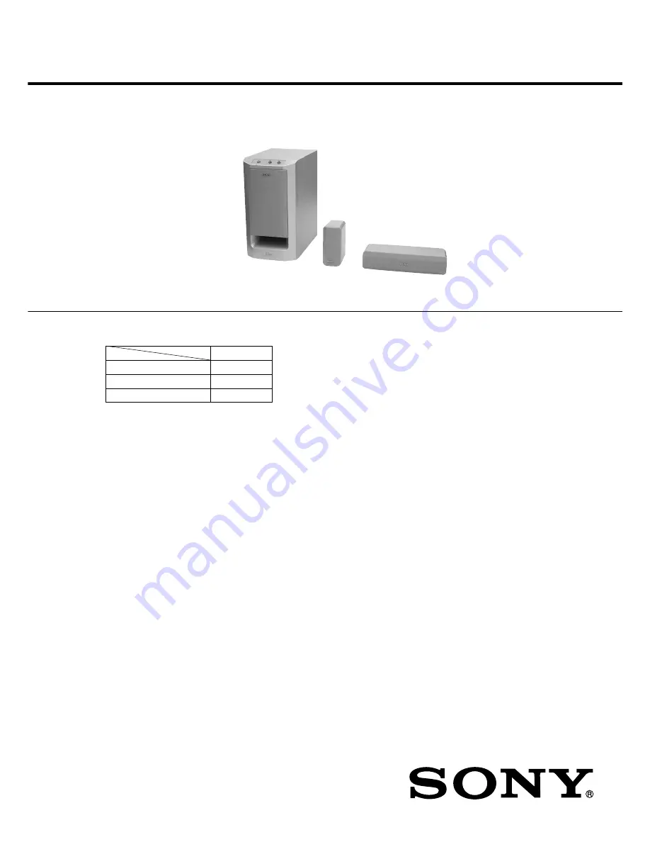
MICRO SATELLITE SYSTEM

AEP Model

UK Model

Ver 1.0  2001.02

9-929-575-11

Sony Corporation

2001B0500-1

Audio Entertainment Group

C

 2001.2

General Engineering Dept.

SPECIFICATIONS

SA-VE225/WMS225/

SS-CN225/V225

• SA-VE225 consists of the following models respectively.

SA-VE225

Active Subwoofer

SA-WMS225

Center Speaker

SS-CN225

Front and Rear Speakers

SS-V225

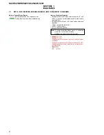
SAFETY-RELATED  COMPONENT  WARNING!!

COMPONENTS  IDENTIFIED  BY  MARK  

0

  OR  DOTTED

LINE  WITH  MARK  

0

  ON  THE  SCHEMATIC  DIAGRAMS

AND  IN  THE  PARTS  LIST  ARE  CRITICAL  TO  SAFE
OPERATION.  REPLACE  THESE  COMPONENTS  WITH
SONY  PARTS  WHOSE  PART  NUMBERS  APPEAR  AS
SHOWN  IN  THIS  MANUAL  OR  IN  SUPPLEMENTS  PUB-
LISHED  BY  SONY.

SA-WMS225

SS-V225

SS-CN225

Содержание SA-VE225

Страница 1: ...off frequency 200 Hz Inputs LINE IN input pin jack SPEAKER IN input terminals Outputs LINE OUT output pin jack SPEAKER OUT output terminals General Power requirements 220 230 V AC 50 60 Hz Power consumptions 50 W Dimensions w h d Approx 205 385 385 mm including front grille Mass Approx 10 5 kg Supplied accessories Foot pads 20 Monaural connecting cord 1 phono to 1 phono 1 Speaker connecting cords ...

Страница 2: ...cated except for electrolytics and tantalums All resistors are in Ω and 1 4 W or less unless otherwise specified 2 nonflammable resistor 5 fusible resistor C panel designation A B Line B B Line Voltages are dc with respect to ground under no signal conditions Voltages are taken with a VOM Input impedance 10 MΩ Voltage variations may be noted due to normal produc tion tolerances Signal path F AUDIO...

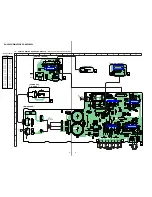
Страница 3: ...S 14 15 12 13 10 11 8 9 6 7 5 3 4 1 2 MOS OUTPUT STAGE SHORT CIRCUIT PROTECTION 1 2 3 4 5 6 7 8 OVER LOAD DET F F OFFSET DET LATCH AUTORESET VCC ON MUTE AC OFF DET OVER LOAD DET OFFSET DET AUTO RESET AC OFF DET GND RELAY DRIVE VCC ON MUTE VCC IC Block Diagrams MAIN Board IC302 µPC1237HA Circuit Boards Location SA WMS225 POWER IC board POWER SW board LED board CONTROL board MAIN board POWER IC Boar...

Страница 4: ... r 1 676 713 LINE 1 677 993 1 676 714 1 676 565 R102 R101 R103 R104 1 2 A B C D E F G H 3 4 5 6 7 8 9 10 11 1 2 PRINTED WIRING BOARDS SA WMS225 See page 3 for Circuit Boards Location Semiconductor Location Ref No Location D101 G 11 D102 F 11 D103 G 10 D104 G 10 D301 F 8 D302 F 8 D303 F 5 D304 D 8 D501 G 5 D502 G 7 D503 H 7 D801 B 7 IC101 G 11 IC102 G 9 IC103 E 11 IC201 B 3 IC302 E 10 IC401 B 10 Q1...

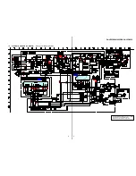
Страница 5: ...2 MIX AMP 1 2 1 2 HIGH PASS FILTER 2 2 LOW PASS FILTER 2 2 1A 250V BUFFER 1 2 3 2 1 2 2 CHASSIS D304 1SS133 7P 7P RBA 402 SL RBA 402 SL RBA 406B 1 3 SCHEMATIC DIAGRAM SA WMS225 See page 3 for IC Block Diagrams The components identified by mark 0 or dotted line with mark 0 are critical for safety Replace only with part number specified ...

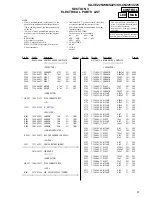
Страница 6: ... Ref No Part No Description Remark Ref No Part No Description Remark 1 X 4952 542 1 FRAME ASSY GRILLE BLACK 1 X 4953 558 1 FRAME ASSY GRILLE SILVER 2 X 4952 603 1 PANEL ASSY FRONT BLACK 2 X 4953 559 1 PANEL ASSY FRONT SILVER 3 4 973 938 41 KNOB A PUSH BLACK 3 4 973 938 71 KNOB A PUSH SILVER 4 4 227 298 01 SHEET 5 4 226 228 01 KNOB VOL BLACK 5 4 226 228 11 KNOB VOL SILVER 7 1 676 565 11 LED BOARD 8...

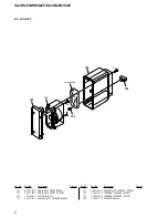
Страница 7: ...ACK 101 X 4953 560 1 PANEL ASSY FRONT SILVER 102 3 703 564 31 SCREW DIA 3 5 103 X 4952 575 1 CABINET ASSY SPEAKER BLACK 103 X 4953 561 1 CABINET ASSY SPEAKER SILVER 104 1 694 516 11 TERMINAL SPEAKER BLACK 104 1 694 516 21 TERMINAL SPEAKER SILVER SP2 1 529 578 11 SPEAKER 5X9cm SP3 1 529 578 11 SPEAKER 5X9cm 101 not supplied 103 102 104 1 SP2 SP3 5 5 ...

Страница 8: ...ANEL ASSY FRONT BLACK 151 X 4953 562 1 PANEL ASSY FRONT SILVER 152 3 703 564 31 SCREW DIA 3 5 153 X 4952 573 1 CABINET ASSY SPEAKER BLACK 153 X 4953 563 1 CABINET ASSY SPEAKER SILVER 154 1 164 516 11 TERMINAL SPEAKER BLACK 154 1 164 516 21 TERMINAL SPEAKER SILVER SP4 1 529 577 11 SPEAKER 5X9cm 151 SP4 153 1 5 154 152 not supplied ...

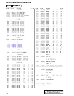
Страница 9: ... uA µA uPA µPA uPB µPB uPC µPC uPD µPD CAPACITORS uF µF COILS uH µH The components identified by mark 0 or dotted line with mark 0 are critical for safety Replace only with part number specified When indicating parts by reference number please include the board A 4720 478 A MAIN BOARD COMPLETE CAPACITOR 0C1 1 113 924 11 CERAMIC 0 0047uF 20 250V 0C2 1 113 924 11 CERAMIC 0 0047uF 20 250V C101 1 162 ...

Страница 10: ...ON 100K 5 1 4W R115 1 249 429 11 CARBON 10K 5 1 4W R116 1 247 843 11 CARBON 3 3K 5 1 4W R117 1 249 424 11 CARBON 3 9K 5 1 4W R118 1 249 436 11 CARBON 39K 5 1 4W R119 1 249 417 11 CARBON 1K 5 1 4W R120 1 249 435 11 CARBON 33K 5 1 4W R121 1 249 425 11 CARBON 4 7K 5 1 4W R122 1 249 439 11 CARBON 68K 5 1 4W R123 1 249 417 11 CARBON 1K 5 1 4W R124 1 249 435 11 CARBON 33K 5 1 4W R125 1 249 425 11 CARBON...

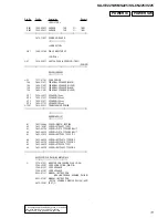
Страница 11: ...5X9cm 0T501 1 435 895 11 TRANSFORMER POWER HARDWARE LIST 1 7 621 846 40 SCREW M4X16 TAPPING 2 7 685 165 01 SCREW PTP 4X25 TYPE1 3 7 685 647 79 SCREW P 3X10 TYPE2 NON SLIT 4 7 685 648 79 SCREW P 3X12 TYPE2 NON SLIT 5 7 685 659 79 SCREW BVTP 4X8 TYPE2 IT 3 6 7 685 660 19 SCREW BVTP 4X10 TYPE2 N S 7 7 685 663 79 SCREW BVTP 4X16 TYPE2 N S 8 7 685 664 79 SCREW PTP 4X20 TYPE1 9 7 685 665 79 SCREW BVTP 4...

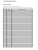
Страница 12: ...EVISION HISTORY Clicking the version allows you to jump to the revised page Also clicking the version at the upper right on the revised page allows you to jump to the next revised page Ver Date Description of Revision 1 0 2001 02 New ...

Отзывы: