background image

Ch
ap
te

6  
 A
d

v

a

nc
ed
 O
p

er

at

io

ns

101

Advanced Effect Operations

To add afterimages

Notes

• Trails are added to both channels of 2-channel effects. 

They cannot be added to nor adjusted for individual 
channels.

• When Trail is enabled, Shadow 

(see page 102)

 is 

disabled.

1

Press the [TRAIL/SHDW] button in the Effect/Wipe 
control block, turning it on.
Or, in the Effect/Wipe >M/E Effect > Trail/Shadow 
menu, turn [Trail/Shdw] on.

2

Press [Type].

A popup window appears.

3

Select [Trail].

4

Set the following parameter with knob 1.

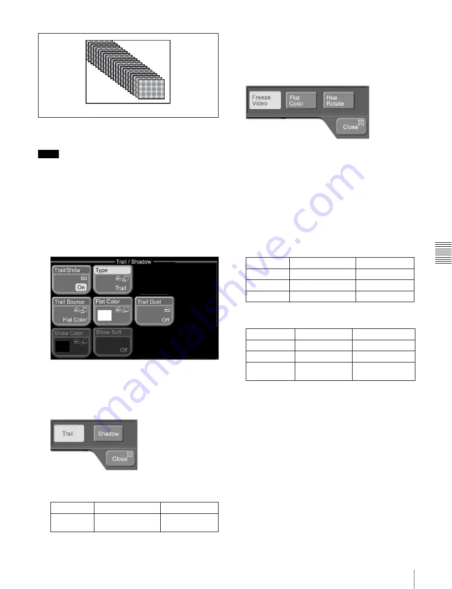
To select the image to use in afterimages

1

In the Effect/Wipe >M/E Effect >Trail/Shadow menu, 
press [Trail Source].

A popup window appears.

2

Select one of the following as the image to insert into 
afterimages.

Freeze Video: 

Freeze images from the input video.

Flat Color:

 Single-color matte.

Hue Rotate: 

Single-color mattes, with the hue 

changing for each frame.

3

If you selected Flat Color or Hue Rotate in step 

2

adjust the following parameters.

Flat Color:

Hue Rotate:

To set afterimage colors from a menu

When the image in afterimages is Flat Color, you can press 
[Flat Color] and set the color from the popup window 
which appears.

See page 55 for more information about how to set the 
color.

To transform afterimages into stardust

The afterimage portion becomes stardust, and gradually 
disappears.

1

In the Effect/Wipe >M/E Effect >Trail/Shadow menu, 
turn [Trail Dust] on.

Knob

Description

Setting values

1 (Decay)

Degree to which the 
trail is left

0.00 to 100.00

Trail

Knob

Description

Setting values

1 (Lum)

Luminance

0.00 to 100.00

2 (Sat)

Saturation

0.00 to 100.00

3 (Hue)

Hue

359.99 to 0.00 

Knob

Description

Setting values

1 (Lum)

Luminance

0.00 to 100.00

2 (Sat)

Saturation

0.00 to 100.00

3 (Hue Speed) Speed at which 

the hue changes

–100.00 to +100.00

Содержание MFS-2000

Страница 1: ...Multi Format Switcher System MFS 2000 System With MKS 2010 MKS 2015 MKS 2017 Control Panel User s Guide English 1st Edition Revised 1 Software Version 2 00 and Later ...

Страница 2: ...OF MERCHANTABILITY OR FITNESS FOR ANY PARTICULAR PURPOSE WITH REGARD TO THIS MANUAL THE SOFTWARE OR SUCH OTHER INFORMATION IN NO EVENT SHALL SONY CORPORATION BE LIABLE FOR ANY INCIDENTAL CONSEQUENTIAL OR SPECIAL DAMAGES WHETHER BASED ON TORT CONTRACT OR OTHERWISE ARISING OUT OF OR IN CONNECTION WITH THIS MANUAL THE SOFTWARE OR OTHER INFORMATION CONTAINED HEREIN OR THE USE THEREOF Sony Corporation ...

Страница 3: ... 40 Setting Parameters 40 Exiting the Menu System 42 Chapter 4 Basics of Video Switching Basic Operations 1 Video Switching on the M E Bank 44 Basic Operations 2 Video Switching on the PGM PST Bank For 1 5 M E Systems 47 Chapter 5 Basic Operations Selecting Video 49 Flow of Operations 49 Selecting Video in the M E Cross Point Control Block 50 Selecting Video in the PGM PST Cross Point Control Bloc...

Страница 4: ...lecting the Color Correction Signal 111 Output of Color Correction Results 111 Flow of Color Correction Operations 111 CCR Menu 111 Input Video Processing 112 Primary Color Correction 113 Secondary Color Correction 114 RGB Clip 115 Luminance Processing 115 Spot Color Adjustment 117 Output Video Processing 118 YUV Clip 118 Frame Memory 119 Overview 119 Flow of Frame Memory Operations 119 Preparatio...

Страница 5: ...t Output Assign Menu 155 Assigning Signals to Cross Point Buttons Operation Menu 156 Saving Setup Startup Mode Menu 160 Installing Software 161 Displaying Version Information Version Information Menu 161 Displaying Detail Information Detail Information Menu 161 Manually Installing Software Manual Install Menu 161 Entering an Installation Key License Menu 162 Other Settings 164 Setting the Date and...

Страница 6: ...6 Table of Contents ...

Страница 7: ...ration the system supports a wide variety of effect patterns including advanced wipes Installation of the optional MKS 2470 DME Board Set makes a further array of advanced effects available such as flip tumble page turn and 2ch P in P two channel picture in picture Comprehensive keying capabilities The system is equipped with two keyers and two downstream keyers All keyers support chroma keying an...

Страница 8: ...rade Software HK PSU02 Power Supply Unit for MFS 2000 HK PSU11 Power Supply Unit for control panels For more information about the above options refer to the MFS 2000 C Operation Manual supplied with the MFS 2000 Multi Format Switcher Processor MKS 2700 Device Control Unit MKS 8700 Device Control Unit For more information about the above options refer to the DCU 2000 or DCU 8000 Operation Manual s...

Страница 9: ...and Functions of Parts Control Panel Types In this system you can use any one of the three control panels shown on the following page This manual refers to these control panels by the names shown in parentheses in the figure on that page ...

Страница 10: ...2 AUX3 AUX4 EDIT PVW UTIL KEY1 KEY2 DSK1 DSK2 CCR1 CCR2 FRAME MEM AUX DELEGATION A POWER MENU MACRO FRAMES FRAMES BLACK N R REV POS M E 1CH M E 2CH LIGHT TRAIL SHDW BVLD EDGE BORD SOFT CROP MENU P P CTR EDIT REG FILE DIAG GPI SAFE TITLE SET UP B EFF WIPE SNAP SHOT PP ALL BANK SEL TRANS RATE M E MCRO STORE 7 8 9 4 5 6 1 2 3 10 EFF DISS AUTO TRNS NEXT TRANSITION OVER OVER KEY PRIOR BKGD KEY1 KEY2 TR...

Страница 11: ...L KEY1 KEY2 DSK1 DSK2 CCR1 CCR2 FRAME MEM AUX DELEGATION A POWER MENU MACRO FRAMES FRAMES BLACK N R REV POS M E 1CH M E 2CH LIGHT TRAIL SHDW BVLD EDGE BORD SOFT CROP MENU P P CTR EDIT REG FILE DIAG GPI SAFE TITLE SET UP B EFF WIPE SNAP SHOT PP ALL BANK SEL TRANS RATE M E MCRO STORE 7 8 9 4 5 6 1 2 3 10 EFF DISS AUTO TRNS NEXT TRANSITION OVER OVER KEY PRIOR BKGD KEY1 KEY2 TRANSITION TYPE KEY1 MIX E...

Страница 12: ...DSK2 CCR1 CCR2 FRAME MEM AUX DELEGATION A POWER MENU EFFECT MACRO FRAMES BLACK EDIT REG FILE DIAG GPI SET UP B SNAP SHOT ALL BANK SEL TRANS RATE M E MCRO EFF STORE 7 8 9 4 5 6 1 2 3 10 EFF DISS AUTO TRNS NEXT TRANSITION OVER OVER KEY PRIOR KEY1 ON BKGD KEY1 KEY2 KEY2 ON TRANSITION TYPE MIX EFF AUTO TRANS CUT PST COLOR MIX DSK1 DSK2 TOP SHUT DOWN SAFE TITLE N R REV POS M E 1CH M E 2CH LIGHT TRAIL S...

Страница 13: ...e 174 The buttons in the A row and the B row select the same signals For example the fifth button from left in the A row selects the same signal as the fifth button from left in the B row You can use the Xpt Assign menu to freely change the assignment of signals to cross point buttons For details see Assigning Signals to Cross Point Buttons Operation Menu page 156 Cross point button numbers On the...

Страница 14: ...trol block see page 12 The meaning of the colors in which buttons light and button numbers are also the same The M E buttons at the right edge of each cross point button row are reentry buttons They allow you to import video created in the M E block and use it as background video in the PGM PST block b XPT cross point HOLD button By pressing this button to turn it on it lights in amber you can rec...

Страница 15: ... red high tally if signals on the selected bus are being output to the program video final output video Otherwise it lights in amber low tally Buttons which target two buses KEY1 KEY2 DSK1 DSK2 and FRAME MEM light in red if signals on either of the buses are being output to program video b SRC source BUS button When an AUX delegation button which targets two buses KEY1 KEY2 DSK1 DSK2 and FRAME MEM...

Страница 16: ...int control block see page 12 Button numbers and the meaning of the colors in which the buttons light are the same as those of the buttons in the M E cross point control block However the cross point button row in the AUX bus control block contains an M E button and a PGM button which are not present in the M E cross point button rows The M E button selects the M E program video and the PGM button...

Страница 17: ... button turning it on you can reverse the priority of the two keys in the next transition c OVER indicators When key 1 and key 2 are inserted the OVER indicator for the key on top lights d Transition type selection buttons To select the type of transition press one of the following buttons turning it on MIX In a background transition the new video overlaps the current video finally replacing it Du...

Страница 18: ...tons the KEY1 ON and KEY2 ON buttons are also found on the 1 M E panel where they are located in the M E transition control block see page 16 a KEY1 ON and KEY2 ON buttons Press the corresponding button to instantly insert or delete key 1 or key 2 The KEY1 ON button lights in red when key 1 is inserted into the program video final output video Otherwise it lights in amber The KEY2 ON button works ...

Страница 19: ...69 for more information about how to specify transition rates Flexi Pad Control Block Use the Flexi Pad control block in the following four operation modes Effect snapshot mode Snapshot mode Macro mode Transition rate input mode Depending on the operation mode this control block allows you to do the following In effect snaphot mode Recall save and delete effect snapshots Recall effect pattern numb...

Страница 20: ...y recall buttons The configuration of the memory recall buttons changes according to the operation mode selected with the mode selection buttons In effect snapshot mode Comprised of the 0 to 9 buttons a PTN NO pattern number button and an ENTR enter button The state and functions of the 0 to 9 buttons and the ENTR button change depending on the state of the PTN NO button and the STORE button For d...

Страница 21: ...he knobs in the menu control block Parameter assigned to knob 1 The value increases when the joystick is moved to the right and decreases when the joystick is moved to the left Parameter assigned to knob 2 The value increases when the joystick is moved away from you and decreases when the joystick is moved toward you Parameter assigned to knob 3 The value increases when the knob of the joystick is...

Страница 22: ... Control Block a ENABLE UTILITY operation buttons You can assign utility commands to these buttons The following utility commands are assigned by default EDIT button Enables and disables the switcher edit mode GPI button Enables and disables switcher GPI SAFE TITLE button Turns on and off a marker showing the television reception safe area and a cross marker showing the center of the screen Blank ...

Страница 23: ...s on the control panel are enabled Menu Control Block a Top menu selection buttons Select the menu shown in the menu display TOP SHUTDOWN top menu shutdown button REG register menu button FILE file menu button SET UP setup menu button DIAG diagnostics menu button b Knobs Use to adjust parameters shown in the menus Power Indicators Memory Stick Slot USB Connector a Power A and B status indicators T...

Страница 24: ...his system does not support the MagicGate function When using a Memory Stick Duo be sure to use it with a Memory Stick Duo Adaptor MSAC M2 or equivalent If you insert a Memory Stick Duo without using the adaptor there is the possibility that the stick cannot be removed resulting in a serious accident Handling Memory Sticks When using Memory Sticks pay attention to the following points Do not touch...

Страница 25: ...hat button The menus which can be accessed with top menu selection buttons are as follows a The most recently used menu is displayed b Currently not supported To access a menu from the top menu proceed as follows Menus accessed with top menu selection buttons and their functions Button Menu Function Reference page TOP SHUTDOWN Top Shutdown Display the top menu and exit the menu system Page 42 REG ...

Страница 26: ...appears If the menu has three levels a popup window appears so that you can select a third level menu 4 Select a menu from the popup window The third level menu appears Accessing Menus by Double Clicking This manual uses the term double click to refer to the action of pressing a button on the control panel twice in rapid succession comparable to double clicking a computer mouse button You can doub...

Страница 27: ...Frame Memory Recall FM2 VIDEO a Frame Memory Recall FM2 KEY a Frame Memory Recall FM3 VIDEO a Frame Memory Recall FM3 KEY a Frame Memory Recall CCR1 a CCR CCR1 Primary Page 113 CCR2 a CCR CCR2 Primary AUX bus control block cross point button rows COLOR BKGD a Misc Color Bkgd Page 88 FM1 VIDEO a Frame Memory Recall Page 122 FM1 KEY a Frame Memory Recall FM2 VIDEO a Frame Memory Recall FM2 KEY a Fra...

Страница 28: ...KEY2 Key M E Key2 Main EFF Effect Wipe M E Effect Main Page 63 Page 66 Page 71 PST COLOR MIX Misc Transition Page 54 PGM PST transition control block b WIPE Effect Wipe P P Wipe Main PST COLOR MIX Misc Transition Page 54 Flexi Pad control block M E EFF WIPE Effect Wipe M E Effect Main Page 63 Page 66 Page 71 PP ALL EFF WIPE b Effect Wipe P P Wipe Main TRANS RATE Misc Transition Page 70 Effect Wipe...

Страница 29: ... window see page 36 Page number input window see page 38 Basic Screen a Menu page number button This shows the menu screen page number When you press this button the page number input window see page 38 appears Enter a page number in that window to display the desired menu For details about operation see Selecting menus by entering page numbers page 40 1 Menu page number button 2 Back button 3 Fwd...

Страница 30: ...e selected a Key menu or an Effect Wipe menu Main Menu button Displays a menu with frequently used items Detail Menu button Displays a popup window for selecting menus to make detailed settings e Menu title buttons Except for the Top button these buttons display the title of the selected of the selected menu The upper buttons correspond to upper level menus In the example of the previous figure To...

Страница 31: ...ion buttons The following table shows how to interpret other buttons Name Display State Parameter button Value displayed Value can be changed Execute button Not executing function Executing function lit in light purple Status area Button area Function name Lights in light blue when parameters are assigned to knobs Icon Status display ...

Страница 32: ...enus for selection The currently selected button lights in light blue The popup window closes when you press a button in this area Name Display Function Popup icon Open a popup window Numeric keypad icon Open the numeric keypad window the timecode window the hexadecimal keypad window or the page number input window Keyboard icon Open the keyboard window Shortcut icons Switch the menu display Close...

Страница 33: ...s this button turning it on if you want to keep the window open even after pressing a button in the function button area d Page Up Page Down buttons Scroll the function button area up and down in page units e Close button Closes the popup window even when the Window Hold button is on Numeric keypad window timecode window The numeric keypad window or timecode window opens when you press a button wh...

Страница 34: ...imecode is displayed in red if an entered value exceeds the setting range Timecode input examples The following table shows examples of timecode input b Minimum to maximum display Displays the minimum and maximum values that can be set for the parameter Does not display anything in the timecode window Digits entered Display Setting value 1 2 12 00 00 00 12 1 2 2 0 12 20 00 00 12 20 1 2 2 0 5 1 22 ...

Страница 35: ...In the timecode window the button changes into a 00 button g Enter button Confirms the entered value If the value is valid the numeric keypad window or the timecode window closes If the value is not valid the window stays open and the color of the input value display changes to red h Clear button Clears the input However parameter settings are not changed Hexadecimal keypad window The hexadecimal ...

Страница 36: ...lues that can be set for the parameter d Close button Closes the hexadecimal keypad window e Enter button Confirms the entered value If the value is valid the hexadecimal keypad window closes If the value is not valid the hexadecimal keypad window stays open and the color of the input value display changes to red f Clear button Clears the input However parameter settings are not changed Keyboard w...

Страница 37: ...the right in the input string e Close button Closes the keyboard window f Caps Lock button Switches between input of capital letters and lowercase letters g Shift button Enables input of characters on the shift side of the buttons The shift is released when you enter a character h BS backspace button Clears the character immediately before the cursor in the input string 1 Item display 2 Input stri...

Страница 38: ...ow stays open and the color of the input value display changes to red Page number input window The page number input window opens in the basic screen when you press a menu page number button a Input value display Shows the value entered in the page number input window b Item display Shows that the value you are entering is a page number c Clear button Clears the input value d Enter button Confirms...

Страница 39: ...enu under the Misc menu when you are in the Main menu under a Key menu for the M E bank In this manual menu names and paths are indicated in the fashion Key M E Key1 Main 1 Press Top A popup window for selection of first level menus appears 2 Select Misc The popup window closes and the display changes to the Misc menu The display on the second and third menu title buttons from the top changes to t...

Страница 40: ...electing Functions To select a function press the corresponding button in the button area of the basic screen The selected button lights in light blue Depending on the button a popup window may appear so that you can select further items Functions may also be assigned to knobs See Interpreting buttons page 31 for illustrations of how buttons change in appearance when they are selected Setting Para...

Страница 41: ...tons of parameter group 1 2 are shown first changing to parameter group 2 2 when the More button in the position of knob 5 is pressed Parameter group name Knob 1 Knob 2 Knob 3 Knob 4 Knob 5 Knob Description Setting values 1 Size Size of pattern 0 00 to 100 00 2 Soft Softness of edge width 0 00 to 100 00 3 Density Key density 0 00 to 100 00 4 Pattern Pattern number 1 to 24 Parameter group 1 2 Knob ...

Страница 42: ...the control panel off 1 In the menu control block press the TOP SHUTDOWN button The top menu appears 2 Press Shutdown A confirmation popup window appears 3 Press Yes This shuts down the menu system after a while and the menu display changes to black Now power off the system To cancel the exit Press No To restart the menu system Power on the control panel once more ...

Страница 43: ...k when a 1 5 M E panel or 1 5 M E wide panel is used The examples in this chapter assume that the following signals are currently selectable with the 2nd 3rd and 4th cross point buttons from the left Signal selectable with the 2nd button from the left Landscape video signal Signal selectable with the 3rd button from the left Lion video signal Signal selectable with the 4th button from the left Cas...

Страница 44: ...fect which the current video is wiped away by new video using a selected pattern The video changes as follows Preparations for operation If you are using the 1 5 M E panel or 1 5 M E wide panel press and light the M E buttons at the right edge of the PGM and PST button rows of the PGM PST cross point control block Before starting move the fader lever from one end of its range to the other and stop...

Страница 45: ...4 There are three ways to select effect patterns In this example we will use the Flexi Pad control block 1 Press the M E button in the Flexi Pad control block lighting it 2 Press the EFF WIPE button in the Flexi Pad control block lighting it 3 Press the PTN NO button lighting it in green 4 With the numeric buttons enter the digits 2 4 in that order The number that you entered appears in the numeri...

Страница 46: ... last time from A bus video to B bus video but this time the lion is replaced by the landscape About auto transitions An auto transition is executed if in step 6 you press the AUTO TRANS button in the transition execution control block instead of moving the fader lever The time from the start to the end of the transition is called the transition rate unit frames The transition rate can be freely s...

Страница 47: ...kground video This section shows how to take the output of the M E bank for example the lion video selected with the 3rd cross point button from the left and use it as background video To replace it we will use the castle video selected with the 4th cross point button from the left As the wipe pattern we will use pattern number 0001 in which the new video gradually moves in from the left side of t...

Страница 48: ...block procced as follows 1 Press the PP ALL button lighting it 2 Press the EFF WIPE button lighting it 3 Press the PTN NO button lighting it in green 4 With the numeric buttons enter the digit 1 The number that you entered appears in the numeric display 5 Press the ENTR button Pattern number 0001 is selected 5 In the PGM PST transition control block slowly move the fader lever down Or press the AU...

Страница 49: ...tion page 73 Compose video by keying page 76 Use internally generated signals page 88 Fade out to black page 93 When mix or preset color mix is selected Advanced operations Advanced effect operations page 95 a Advanced key operations page 104 Select video page 49 a Some patterns cannot be modified in this way For details refer to Effect Pattern Transformations and Modifications in the Appendix sep...

Страница 50: ...buttons in the background A row Select the background video displayed after the transition with the buttons in the background B row The following table shows the correspondences between selectable signals and the cross point buttons used to select them in the factory default configuration a IN1 to IN16 when using the 1 5 M E wide panel Assignments of signals to cross point buttons can be freely ch...

Страница 51: ...w Selecting Video in the AUX Bus Control Block In the AUX bus control block you can use the AUX delegation buttons to assign the cross point button row to the desired bus allowing you to select key signals and signals to apply a variety of other functions The buses which can be selected by the AUX delegation buttons are as follows For more information about the buttons in the AUX bus control block...

Страница 52: ...m video the corresponding button lights in red high tally Otherwise the button lights in amber low tally To select the background of a 2 channel effect In some of the effect patterns from number 2001 to number 2999 utility bus signals are used as the background for the A bus and B bus video For such effect patterns first press the AUX delegation button UTIL and then press a button in the cross poi...

Страница 53: ...deo by keying page 76 Use internally generated signals page 88 Fade out to black page 93 When mix or preset color mix is selected Advanced operations Advanced effect operations page 95 a Advanced key operations page 104 Select video page 49 a Some patterns cannot be modified in this way For details refer to Effect Pattern Transformations and Modifications in the Appendix separate document Change t...

Страница 54: ... is a two stage mix dissolve comprising two transitions In the first transition a color matte non patterned color signal is gradually mixed into the current video In the second transition the new video is gradually mixed into the color matte When this is selected you can use the following procedure to select the matte color To select a color matte for preset color mix 1 From the top menu select Mi...

Страница 55: ...ition Press one of the next transition selection buttons in the M E transition control block lighting the button This operation is not needed for a transition in the PGM PST bank since only the background changes BKGD The background changes KEY1 Insert or delete key 1 KEY2 Insert or delete key 2 KEY PRIOR Reverse the priority of key 1 and key 2 See Composing Video With Keys page 76 for more inform...

Страница 56: ...i Pad control block or menus Basic operations Always done Done as required Done at this stage Modify the video border page 66 a Prepare the transition page 69 Execute the transition page 73 Compose video by keying page 76 Use internally generated signals page 88 Fade out to black page 93 When mix or preset color mix is selected Advanced operations Advanced effect operations page 95 a Advanced key ...

Страница 57: ...utton lighting it in green The PTN NO button lights alternately in green and orange each time it is pressed An effect number can be entered now 4 Enter the number of the desired effect pattern If the number begins by 0 00 or 000 it is needless to input these zeros For example when the number is 0001 input the digit 1 only Wipe pratterns selectable in the PGM PST bank are limited to 0001 to 0024 09...

Страница 58: ...O button so that it changes back to lit in orange then repeat the procedure from step 3 5 Press the ENTR button This confirms the effect pattern number entered in step 4 When an invalid pattern number is entered A warning tone sounds and the system exits pattern number input mode Check the correct pattern number and repeat from step 3 Selecting Effects From Menus 1 From the top menu select Effect ...

Страница 59: ...h rotation scrolls 1 line up or down Press Page Down or Page Up Each press scrolls 3 lines up or down 3 To select the desired pattern from a group of patterns press Group Select A popup window appears 4 Select the name of the desired group The effect patterns in the selected group appear The example in the following figure shows the Enhanced group ...

Страница 60: ... Key priority KEY PRIOR has been selected as the transition type Transition effects and non transition effects Effects numbered 1001 and higher fall into the following two types depending on what occurs when the effect is executed Transition effects slides page turn etc A bus and B bus cross points are switched by executing a transition Also when border cropping or other modifications 1 have been ...

Страница 61: ... lighting the button You can also select both channels To select channels from menus Note Two channels cannot be selected at once from a menu However when two channels are selected with the buttons in the Effect Wipe control block both of the buttons are lit in the menu 1 From the top menu select Effect Wipe M E Effect Main The Main menu appears 2 Press M E 1ch or M E 2ch to select a channel If tw...

Страница 62: ...cts they are set for both channels Position of the Ripple 2ch effect Crop of the Page Roll 2ch effect Crop of the Page Turn 2ch effect Parameters common to both channels Parameters other than the above are set for both channel 1 and channel 2 even if only one of the channels has been selected with the M E 1CH and M E 2CH delegation selection buttons ...

Страница 63: ...age 66 a Prepare the transition page 69 Execute the transition page 73 Compose video by keying page 76 Use internally generated signals page 88 Fade out to black page 93 When mix or preset color mix is selected Advanced operations Advanced effect operations page 95 a Advanced key operations page 104 Select video page 49 a Some patterns cannot be modified in this way For details refer to Effect Pat...

Страница 64: ...nnels 3 Operate the joystick as shown below depending on what you want to change a Not available for some patterns For details refer to Effect Pattern Transformations and Modifications in the Appendix separate document To return the pattern size and position to their default Press the CTR button in the Effect Wipe control block Changing Pattern Size and Position From Menus 1 From the top menu sele...

Страница 65: ...0 moves it to the right edge b 100 00 moves the center of the pattern to the bottom edge and 100 00 moves it to the top edge c Not available for some patterns For details refer to Effect Pattern Transformations and Modifications in the Appendix separate document To return the pattern to the center of the screen in a transition effect pattern nos 0001 to 0999 only In the Effect Wipe M E Effect Main...

Страница 66: ... Execute the transition page 73 Compose video by keying page 76 Use internally generated signals page 88 Fade out to black page 93 When mix or preset color mix is selected Advanced operations Advanced effect operations page 95 a Advanced key operations page 104 Select video page 49 a Some patterns cannot be modified in this way For details refer to Effect Pattern Transformations and Modifications ...

Страница 67: ...menu see page 61 select the channel or channels for which you want to make settings You can set parameters for the individual channels Note that for effects other than 2 channel effects it is not necessary to carry out channel selection Begin with step 2 2 Press Border Color A popup window appears displaying the same 8 colors as a color bar 3 Press the button for the color that is closest to the d...

Страница 68: ...Set the following parameters with the knobs No borders Borders a Not displayed for effect patterns nos 1001 to 2999 Knob Description Setting values 1 Lum Luminance 0 00 to 100 00 2 Sat Saturation 0 00 to 100 00 3 Hue Hue 359 99 to 0 00 Knob Description Setting values 1 Soft Softness of edges 0 00 to 100 00 Knob Description Setting values 1 Width Width of borders 0 00 to 100 00 2 Inner Soft Softnes...

Страница 69: ...6 Execute the transition page 73 Compose video by keying page 76 Use internally generated signals page 88 Fade out to black page 93 When mix or preset color mix is selected Advanced operations Advanced effect operations page 95 a Advanced key operations page 104 Select video page 49 a Some patterns cannot be modified in this way For details refer to Effect Pattern Transformations and Modifications...

Страница 70: ...ion buttons Press M E to set for the M E bank Press PP ALL to set for the PGM PST bank when using the 1 5M E panel 3 Enter the transition rate as a number of frames The setting range is 0 to 999 4 Press the ENTR button This confirms the input The transition rate appears beneath the fader lever in the transition control block To set transition rates from menus 1 From the top menu select Misc Transi...

Страница 71: ...ms the input The transition rate appears beneath the fader lever in the transition control block Selecting Effect Directions You can select the direction of some effects The normal direction is the direction of the arrows shown in the illustrations of effect patterns in the Effect Pattern List in the Appendix separate document The reverse direction is the opposite direction s To select effect dire...

Страница 72: ...so that it is not lit To select the normal reverse direction Press the N R button so that it lights To select effect directions from menus 1 From the top menu select Effect Wipe M E Effect Main The Main menu appears 2 Select one of the following To select the normal direction Turn both Norm Rev and Reverse off To select the reverse direction Turn Reverse on and turn Norm Rev off To select the norm...

Страница 73: ...6 Use internally generated signals page 88 Fade out to black page 93 When mix or preset color mix is selected Advanced operations Advanced effect operations page 95 a Advanced key operations page 104 Select video page 49 a Some patterns cannot be modified in this way For details refer to Effect Pattern Transformations and Modifications in the Appendix separate document Change the position and size...

Страница 74: ... which light one after the other as the transition proceeds To execute a transition with the fader lever Move the transition lever from one side to the other at any speed Once you do this you can control the transition manually The transition indicator LEDs light one after the other as you move the lever to execute the transition About fader lever non sync If an auto transition finishes with the f...

Страница 75: ...cute a transition with the next operation Moving the lever toward the side where LEDs are not lit executes a transition across the remaining lever range An auto transition is possible even if the fader lever is in a non sync state When you press the AUTO TRANS button the transition indicator LEDs light as always to show the progress of the transition But when the transition finishes two of the LED...

Страница 76: ... pattern is used as the key source Flow of Operations The following figure shows a typical flow of operations when using the MFS 2000 system For details about operations see the pages in parentheses Basic operations Always done Done as required Done at this stage Select an effect page 56 Prepare the transition page 69 Use internally generated signals page 88 Fade out to black page 93 When mix or p...

Страница 77: ...t With a Luminance Key or Linear Key A linear key is a type of luminance key but with less variation in gain allowing more precise adjustment The following procedure shows how to set up key 1 on the M E bank The same operations can be used with the other keys as well key 2 and downstream keys 1 and 2 To select luminance or linear key and set the key parameters 1 From the top menu select Key M E Ke...

Страница 78: ...rom the key source signal selected automatically in Auto Select mode another key source may be selected independently If you select this proceed to step 3 and select the key source 3 If you selected Split in step 2 press the KEY1 button and the SRC BUS button in the AUX bus control block lighting both buttons and select a key source in the cross point button row The state of the KEY button determi...

Страница 79: ...tor When this is selected you can select the matte color as explained in the next section To adjust the key fill color 3 If you selected Key Bus in step 2 first press the KEY1 button in the AUX bus control block lighting it then press the SRC BUS button extinguishing it and finally select the key fill from the cross point button row See the following figure KEY1 button SRC BUS button lit Cross poi...

Страница 80: ... Press the button for the color that is closest to the desired color The popup window closes 3 Set the following parameters with the knobs To insert and delete keys Use transitions to insert keys into background video and to delete keys from background video KEY1 button Cross point button row 1 5 M E panel 1 M E panel KEY1 button SRC BUS button not lit Cross point button row SRC BUS button not lit...

Страница 81: ...7 2 Press Chroma To select a chroma key source Refer to step 1 in To select a key source page 78 in the procedure for luminance and linear keys To select a chroma key fill Referring to the procedure for luminance and linear keys in To select a key fill page 79 set the key fill to Key Bus and select the key fill with the cross point buttons To adjust auto chroma key 1 In the Key M E Key1 Main menu ...

Страница 82: ...w to set up key1 on the M E bank The same operations can be used to set up the other keys as well key 2 and downstream keys 1 and 2 1 In the Key M E Key1 Main menu see page 77 press Key Type A popup window appears see page 77 2 Press Pattern 3 Set the following parameters with the knobs a Same as standard wipes Knob Description Setting values 1 H Position Move the sample mark horizontally 100 00 t...

Страница 83: ...g the Pattern of a Pattern Key page 109 Adding Borders to Keys The following procedure shows how to add borders to key1 on the M E bank The same operations can be used to add borders to the other keys as well key 2 and downstream keys 1 and 2 1 In the Key M E Key1 Main menu see page 77 press Edge A popup window appears 2 Press one of the following Normal Do not add anything to the edges Border Add...

Страница 84: ...nu select Key M E Key1 Main and press Edge Color A popup window appears 2 Press the button for the color that is closest to the desired color and adjust the parameters with the knobs See To adjust the key fill color page 80 for the parameters Masking Part of a Key A mask is used to cover part of the video with background or a key This allows you to correct for unwanted holes in the background or a...

Страница 85: ...d mask settings see Setting Key Mask Shapes and Positions page 109 Moving a Key Over or Under To check whether a key is over or under There are OVER indicators in the M E transition control block located over key1 and key2 The key whose OVER indicator is lit is the key on top To move a key over or under from menus The following procedure shows how to move key1 on the M E bank The same operations c...

Страница 86: ...et up downstream key 1 The same operations can be used to set up the other keys as well M E keys 1 and 2 and downstream key 2 1 From the top menu select Misc Transition The Transition menu appears see page 54 2 After pressing DSK1 enter the key s transition rate in the numeric keypad window See Setting Transition Rates page 69 3 In the downstream key fade to black control block press the AUTO TRAN...

Страница 87: ... or delete M E keys instantly If you are using the 1 5M E panel press the KEY1 ON button or the KEY2 ON button in the M E key transition control block If you are using the 1 M E panel press the KEY1 ON button or the KEY2 ON button in the M E transition control block ...

Страница 88: ...re the transition page 69 Fade out to black page 93 When mix or preset color mix is selected Advanced operations Advanced effect operations page 95 a Advanced key operations page 104 Select video page 49 a Some patterns cannot be modified in this way For details refer to Effect Pattern Transformations and Modifications in the Appendix separate document Change the position and size of the effect pa...

Страница 89: ...indow appears 3 Press the button for the color that is closest to the desired color 4 Set the following parameters with the knobs To compose a pattern of two colors color mix 1 From the top menu select Misc Color Bkgd then press Mix Color turning it on Color background single color Knob Description Setting values 1 Lum Luminance 0 00 to 100 00 2 Sat Saturation 0 00 to 100 00 3 Hue Hue 359 99 to 0 ...

Страница 90: ...ter is at the left edge of the screen At 100 00 it is at the right edge b Minus values move the pattern down and plus values move it up At 100 00 the vertical center is at the bottom edge of the screen At 100 00 it is at the top edge To arrange multiple examples of the same pattern 1 From the top menu select Misc Color Bkgd then press Multi turning it on 2 Adjust the following parameters with the ...

Страница 91: ... direction To rotate an effect pattern at a specified speed 1 From the top menu select Misc Color Bkgd then press Rotation A popup window appears 2 Press Speed 3 Set the following parameter with knob 1 a 100 00 is one rotation per second in the counterclockwise direction and 100 00 is one rotation per second in the clockwise direction To modulate an effect pattern Note The shape of the modulation ...

Страница 92: ... in the right direction In V Modulation maximum speed is at 100 00 in the downward direction and 100 00 in the upward direction To exchange color 1 and color 2 From the top menu select Misc Color Bkgd then press Color Invert turning it on The data for color 1 and color 2 are exchanged Knob Description Setting values 1 Amplitude Amplitude of modulation wave 0 00 to 100 00 2 Frequency Frequency of m...

Страница 93: ...page 88 When mix or preset color mix is selected Advanced operations Advanced effect operations page 95 a Advanced key operations page 104 Select video page 49 a Some patterns cannot be modified in this way For details refer to Effect Pattern Transformations and Modifications in the Appendix separate document Change the position and size of the effect pattern page 63 a Color correction page 111 Fr...

Страница 94: ...pad window See Setting Transition Rates page 69 3 In the downstream key fade to black control block press the FTB button The FTB button lights and the fade to black begins When it finishes the picture is completely black To stop the fade to black and return to the state before it started press the button again To return to the original video from a black screen Press the FTB button again 3 1 2 1 3...

Страница 95: ... the Appendix separate document To change the aspect ratio of an effect pattern Aspect 1 From the top menu select Effect Wipe M E Effect Modify Ptn 1 999 The Modify Ptn No 0001 0999 menu appears 2 Press Aspect turning it on 3 Set the aspect ratio parameter with knob 1 a Minus values make the pattern taller and plus values make the pattern longer To rotate an effect pattern Rotation 1 In the Effect...

Страница 96: ...n the left direction and 100 00 in the right direction In V Modulation maximum speed is at 100 00 in the downward direction and 100 00 in the upward direction b 1 Sine wave 2 Triangular wave 3 Rectangular wave To arrange several examples of the same effect pattern Multi 1 In the Effect Wipe M E Effect Modify Ptn No 0001 0999 menu see page 95 press Multi turning it on 2 Set the following parameters...

Страница 97: ...d Modifications in the Appendix separate document 1 Press the CROP button in the Effect Wipe control block turning it on Or in the Effect Wipe M E Effect Crop menu turn Crop on 2 Select the operating channels See Selecting Channels page 61 3 Set the following parameters with the knobs To crop to 4 3 in 16 9 mode In HD format 16 9 mode you can crop the video to 4 3 1 Press the CROP button in the Ef...

Страница 98: ...ion has elapsed Adding Beveled Edges to Video This operation can only be carried out on M E effects It is not supported for some patterns For more information refer to Effect Pattern Transformations and Modifications in the Appendix separate document Light mode and color mode You can add beveled edges in light mode or color mode Light mode Beveled edges are produced by varying the brightness at th...

Страница 99: ...close to light source 0 00 to 200 00 a 2 Inten 2 Luminance of edges on side away from light source 0 00 to 200 00 a 3 Angle Direction of light source 100 00 to 100 00 b 2 1 1 2 1 2 1 2 Example Changing the angle value Inten 1 80 Inten 2 180 Intensity 1 Intensity 2 Intensity 1 Intensity 2 Intensity 2 Intensity 1 Intensity 1 Intensity 2 Angle Angle The edges corresponding to Inten 1 and Inten 2 chan...

Страница 100: ...pending on the type of lighting used by the selected effect Plane light Preset light Preset shade a 100 is the value of the effect pattern width parameter when the effect pattern was applied b 0 is no lighting 100 is strong lighting c 0 is black To set the light color 1 In the Effect Wipe M E Effect Lighting menu press Light Color A popup window appears 2 Press a button with a color that is close ...

Страница 101: ...r Single color matte Hue Rotate Single color mattes with the hue changing for each frame 3 If you selected Flat Color or Hue Rotate in step 2 adjust the following parameters Flat Color Hue Rotate To set afterimage colors from a menu When the image in afterimages is Flat Color you can press Flat Color and set the color from the popup window which appears See page 55 for more information about how t...

Страница 102: ...the image To set the shadow color 1 In the Effect Wipe M E Effect Trail Shadow menu press Shdw Color A popup window appears 2 Press a button for a color that is close to the color you want 3 Set the following parameters with the knobs To soften the edges of the shadow In the Effect Wipe M E Effect Trail Shadow menu turn Shdw Soft on Composing a Video border Color From Two Colors You can compose th...

Страница 103: ... the knobs Saving Recalling and Deleting Effect Snapshots You can save snapshots of the current effect pattern numbers transformation parameters and so on and recall them for later use These snapshots are called effect snapshots There are ten effect snapshot registers 1 to 10 on each of the M E and P P regions A region means a functional unit block of the system Saving effect snapshots 1 Make the ...

Страница 104: ...button you pressed is turned off and the effect snapshot is deleted Advanced Key Operations This section explains procedures for setting M E key 1 The same procedures can be used for the other keys as well M E key 2 and downstream keys 1 and 2 Processing Key Signals To turn key clean mode on Clean mode In a luminance key or linear key you can enable the clean mode When the clean mode is on the key...

Страница 105: ...ss Mix Color turning it on 3 Set the pattern used to mix the 2 colors and specify color 1 and color 2 See To compose a pattern of two colors color mix page 89 and To transform color mix patterns page 90 for information on how to set the parameters Note that the parameters H Modulation and V Modulation are not available for color mix patterns To set separate border widths Separate Edge function Whe...

Страница 106: ...hen additive mix is selected 1 In the Key M E Key1 Chroma Key menu press Plane turning it on 2 Set the following parameter with knob 1 To adjust chroma keys manually Methods of adjusting the composite obtained from chroma keying include automatic adjustment with the auto chroma key function and manual adjustment carrying out the necessary processing separately The optimum results will be obtained ...

Страница 107: ...ge 108 By using the Y balance function on a color cancel key colors of the same hue as the background typically blue can be output in the foreground without being cancelled 1 In the Key M E Key1 Chroma Key menu press CC Y Balance turning it on 2 Set the following parameter with the knob To adjust the window Chroma keying generates a key signal based on a particular color reference color in the for...

Страница 108: ...ied intensity are treated as shadows there is no effect on cutting out of the foreground 1 In the Key M E Key1 Chroma Key menu press Shadow turning it on 2 Set the following parameters with the knobs Note When chroma key shadowing is on key edges are normal with soft edges off To adjust video signals You can vary the gain and hue of chroma key foreground video Gain can be adjusted for the overall ...

Страница 109: ... When using a pattern key operate in the same way as in For a PGM PST effect in the effect transformation procedure Setting Key Mask Shapes and Positions See Masking Part of a Key page 84 for more information about how to make basic key mask settings 1 From the top menu select Key M E Key1 Mask The Mask menu appears 2 Press Mask Source A popup window appears 3 Select either of the following Box Bo...

Страница 110: ...tput when the button lights Output ends after the specified hold time You can stop show key output by pressing Show Key during the output Using Key Memory The key memory function allows the keyer settings on each cross point button to be automatically stored so that the next time the same cross point button is selected these settings are recalled automatically Key memory operating modes There are ...

Страница 111: ...sign signals to which color correction has been applied to cross point buttons and output the corrected signals by pressing those buttons For details of the assignment process see Selecting Video page 49 Flow of Color Correction Operations Color correction is carried out in the following steps Input video processing see page 112 r Primary color correction see page 113 r Secondary color correction ...

Страница 112: ...om the top menu select CCR Copy Swap The Copy Swap menu appears The status area shows a copy source list From on the left and a copy destination list To on the right 2 Using any of the following methods select the copy source color corrector and the copy destination color corrector Press directly on the list in the status area Use the arrow buttons to scroll the reverse video cursor Turn the knobs...

Страница 113: ...stment Knee correction Unadjusted signal Adjusted signal Knob Description Setting values 1 Red Black balance of R red signal 100 00 to 100 00 2 Green Black balance of G green signal 100 00 to 100 00 3 Blue Black balance of B blue signal 100 00 to 100 00 4 All Black balance of R G and B signals adjusted at once Red value is shown Knob Description Setting values 1 Red White balance of R red signal 0...

Страница 114: ...peration refer to Setting Key Mask Shapes and Positions page 109 6 Referring to CCR Menu page 111 open the Primary menu 7 Press Mask and adjust the following parameters When Box was selected as the mask source When Pattern was selected as the mask source To invert the mask source Press Mask Invert in the Primary menu Secondary Color Correction You can adjust the following across a 30 range around ...

Страница 115: ...uminance Processing You can divide the luminance levels of YUV signals into three regions Dark Middle and Bright and adjust the video signals of each region separately To execute luminance processing Display the Luminance Process menu then proceed as follows 1 Press Lum Proc turning it on 2 Press Mode A popup window appears so that you can select the adjustment mode 3 Depending on what you want to...

Страница 116: ...sition of maximum point of luminance level curve 7 30 to 109 58 Knob Description Setting values 1 Over B Lvl Luminance level at upper limit of Bright region 50 00 to 150 00 2 Mid B Lvl Luminance level at boundary between Bright and Middle regions 10 00 to 120 00 3 D Mid Lvl Luminance level at boundary between Middle and Dark regions 20 00 to 90 00 Output signal luminance level White balance adjust...

Страница 117: ...ge for spot color adjustment 7 Press Spot and adjust the replacement color To return spot color adjustment parameters to their default settings Press Spot Unity To mask part of the spot color adjustment Press Mask in the Spot menu turning it on Then proceed as explained in To mask part of the primary color correction see page 114 To adjust colors outside the spot color adjustment region 1 With Spo...

Страница 118: ... signal level Positive clip Maximum amplitude in positive direction of color difference signal Negative clip Maximum amplitude in Negative direction of color difference signal To execute YUV clip Display the YUV Clip menu then proceed as follows 1 Press YUV Clip turning it on 2 Depending on the signal you want to adjust press one of the following to select the target for adjustment Luminance Lumin...

Страница 119: ...d Set BZS 2440M Frame Memory Upgrade Software However the BZS 2440M software is not required when the signal format is 480i or 576i Flow of Frame Memory Operations The flow of frame memory operations is as follows Assign frame memory output to a cross point r Select the input signal video before freeze etc See page 120 r Freeze the video at the desired point and save an image file in frame memory ...

Страница 120: ...n the auxiliary bus control block as follows To select the video input signal turn the SRC BUS button off The auxiliary bus switches to the frame memory video bus In this case the key assigned as a pair to the selected video is automatically selected on the frame memory key bus To select the key input signal turn the SRC BUS button on The auxiliary bus switches to the frame memory key bus In this ...

Страница 121: ...meric characters For automatic saving the file name is automatically set to auto_000 auto_001 and so on For a key file k is automatically appended to the file name Saving files with Pair on off When saving with Pair turned off a file is created for either the video or key Referred to below as an Single file When Pair is turned on both video and key files are created with the same name Referred to ...

Страница 122: ...ff press one of the output buttons to select it for the operation The selected button turns light blue 5 Do one of the following to select the image file to recall Press directly on the list appearing in the status area Press the list arrow buttons Turn the knob Freeze image selection in the list is reflected in thumbnail selection and vice versa 6 If Pair is off press the Video or Key thumbnail t...

Страница 123: ...cted Select All skip to step 5 3 Select either video or key To delete a video image file press Video above the thumbnail To delete a key image file press Key above the thumbnail The thumbnail button turns yellow The file name in the list also turns yellow indicating that this is the file to be affected 4 To delete more than one file repeat steps 2 and 3 to select the files 5 Press Delete A message...

Страница 124: ...ified by setup settings remain unchanged 1 This can be set independently for each keyer Effect dissolve The transition from the state before the snapshot recall to the snapshot settings is carried out smoothly by a dissolve Auto transition An auto transition starts the instant the snapshot is recalled The auto transition setting is valid for M E and PGM PST 1 There are three hold modes for key bus...

Страница 125: ...ted bank This is also indicated by the display on the memory recall buttons For example the display is as shown below when bank 3 is selected 6 Press the STORE button turning it on The snapshot can now be saved 7 Press the memory recall button corresponding to register in which you want to save the snapshot Note The contents of the corresponding register are overwritten if you press a button which...

Страница 126: ...he selected register number To maintain cross point states temporarily with the bus override function Recall the snapshot while holding down a cross point button in the A or B row on the M E bank or a cross point button in the PGM or PST row on the PGM PST bank The snapshot is recalled without changing the selection of the signal on the bus This operation is not necessary when cross point hold is ...

Страница 127: ...ticular event to delay the start of execution of the event by a particular time interval you can store a special event which pauses macro execution This event is called a pause event When you store a pause event you can set the interval for which the macro is paused the pause duration to any value in the range 1 to 999 frames When the set time has elapsed the macro is automatically executed Pause ...

Страница 128: ...de selection buttons other than the MCRO button TRANSRATE button and so on the executed operation is also registered as an event In this case the MCRO button stays lit red To return to macro edit mode from this state press the MCRO button 8 When auto insert mode is off press the INS button to register the event 9 Repeat steps 7 and 8 to register the required events in the macro This registers the ...

Страница 129: ...serted between the cue up event and the playback event To include all information associated with an operation when registering a macro event When registering an auto transition operation as an event you can register the auto transition event to include the transition rate and background A B bus selection status To use this capability assign the following functions to buttons in the utility contro...

Страница 130: ...ne macro at a time During macro execution recalling the same register again stops the macro being executed Individual events stored in a macro are executed according to the settings in setup If you change the settings in setup a saved macro may not have the expected effect During macro execution if you switch the control panel to macro edit mode the macro being executed stops During macro editing ...

Страница 131: ...NS button to toggle the auto insert mode on or off 3 Carry out the event to be added on the control panel You can include pause events see page 129 When auto insert mode is on execution of a control panel operation automatically registers an event in the macro When auto insert mode is off proceed to step 4 For details of events that can be registered see page 127 4 When auto insert mode is off pre...

Страница 132: ...assign any one of the 99 macro registers to a button For a button whose function is switched by delegation you can make a separate macro attachment for each function You can make up to 1000 macro attachment settings The macro attachment setting is possible for the following bus buttons For button locations see pages in parentheses a Not found on 1 M E panel b When you attach macros to buttons that...

Страница 133: ...macro attached button It results in either of the following When the new setting is made in the same macro attachment mode as for the old setting Both old and new settings are invalid When the new setting is made in a different macro attachment mode from the old setting The new setting is valid Note After setting a macro attachment to a cross point button in the cross point control block if in the...

Страница 134: ...ve reception area of television receivers which is indicated by a box marker appearing on the monitor screen This function also allows you to display a cross marker which indicates the center of the screen See Making safe title settings page 169 for more information about marker types and other safe settings Displaying safe title markers with a menu operation 1 From the top menu select Misc Enable...

Страница 135: ... DSK1 Downstream key 2 DSK2 Using Buttons to Copy Key Settings You can easily copy keyer settings by using the AUX delegation buttons KEY1 KEY2 DSK1 and DSK2 in the AUX bus control block to specify the copy source and copy destination Example Copying M E key 1 to M E key 2 In the AUX bus control block see page 15 hold down the KEY 1 delegation button and press the KEY 2 button A beep sounds and th...

Страница 136: ...Chapter 6 Advanced Operations 136 Copying ...

Страница 137: ...ories Save load and delete all data in all categories except frame memory image data in a single operation Save load and delete all data in selected categories except frame memory image data in a single operation Save load delete rename and copy files containing frame memory image data Notes Data saved to hard disk may become unavailable if trouble occurs on the hard disk It is recommended that im...

Страница 138: ...7 to select the type of media storing the data you want to load 2 In the File All menu press All Load A confirmation window appears asking if you want to execute the load 3 Press Yes in the confirmation window to execute the load or No to cancel it If you pressed Yes the load begins and a window opens to show its progress Note that all existing data in the load destination registers are deleted be...

Страница 139: ...Once see page 137 1 SYSTEM is specified as the target directory No other directory can be selected 6 Press the button for the desired media type Hard Disk or Memory Stick The color of the pressed button is inverted 7 Press OK The popup window closes 8 In the File All Selected menu press Save A confirmation window appears asking if you want to execute the save 9 Press Yes in the confirmation window...

Страница 140: ...To cancel the data deletion after it has started Press Cancel in the progress window and press OK in the message box which appears to inform you that the deletion has been cancelled Operating on Individual Data Files You can save load delete rename and copy files containing frame memory image data Loading Data Files Proceed as follows to load files containing frame memory image data to registers 1...

Страница 141: ...frame memory image data files 1 From the top menu select File Save The Save menu appears The media directory files and registers used in the previous save operation appear in the status area 2 Select the Frame Memory category and as required the target media For details about the procedure see Common Operations Selecting the Frame Memory Category and the Target Media page 144 3 To change the save ...

Страница 142: ...ress Target File A file list appears in a popup window 4 Do one of the following to select the files to delete Press directly on the list in the popup window Use the arrow buttons to scroll the reverse video cursor Turn the knobs 5 When you are finished selecting files press OK The popup window closes 6 In the File Delete menu press Delete A confirmation window appears asking if you want to execut...

Страница 143: ...see Common Operations Selecting the Frame Memory Category and the Target Media page 144 3 In the File Copy menu press Source File A list of copy source files appears in a popup window 4 Do one of the following to select the copy source files Press directly on the list in the popup window Use the arrow buttons to scroll the reverse video cursor Turn the knobs 5 When you are finished selecting files...

Страница 144: ...ayed proceed as follows 1 Press Category Sel A popup window appears 2 Select Frame Memory and press OK The popup window closes 3 To change the media selection from the current selection to the other type press one of the following buttons depending on the file operation A popup window opens 1 SYSTEM is specified as the target directory No other directory can be selected 4 Press the button for the ...

Страница 145: ...nctions which can be controlled via the GPI connector on the rear panel of the processor Auto transitions Cuts Key mix transition Key on and off Preparations The following preparations must be made to control the MFS 2000 system from an external editing system Preparations on the MFS 2000 side To use 9 pin serial control signals Enable the switcher editor mode by doing one of the following Press t...

Страница 146: ...e of the following DCU systems is required MKS 2700 Six RS 422A ports standard equipment MKS 8700 with optional MKS 8702 boards installed Up to five boards may be installed with each board providing six RS 422A ports maximum 30 ports To control external devices assign them to arbitrary RS 422A 9 pin serial interface ports See page 187 for more information about how to make device assignments Manua...

Страница 147: ... Setting start points page 148 for details about operation Cuing up start points Press the Cue Up button as assigned in the Utility menu While the reference device is cued up the CUE button flashes in amber When the cue up ends the button changes to lit in green The All Stop button as assigned in the Utility menu also flashes in amber when any of the devices assigned to the Device1 to Device6 sele...

Страница 148: ...cations Protocol is used When other devices are used XXXX Not communicating or communicating but the device type cannot be read Communications with the device are being carried out normally but status information is not received Local Port is not open The REMOTE LOCAL switch of the device is set to LOCAL Tape Out No file loaded VTR No tape loaded Disk recorder No file loaded Rec a Recording Cue Cu...

Страница 149: ...tions Protocol File lengths and update dates are not displayed for Extended VTRs and register numbers are shown in place of file names 2 Turn the knob to select a player device Note File lists cannot be loaded from disk recorders which are being used as recorders 3 Press List Update Loading of the file list starts and a progress bar appears in a popup window The popup window disappears when loadin...

Страница 150: ...rder set to Recorder Note File update dates are not displayed for disk recorders using the Video Disk Communications Protocol 2 Turn the knob to select the device on which to create the new file Note You will not be able to create a file if you select a disk recorder that is being used as a player 3 Press New File The keyboard window appears 4 Enter a file name and press Enter The maximum file nam...

Страница 151: ...ata link primary station 4 Use the Setup Diag System Initialize menu see page 165 to reboot the system When the reboot finishes connection to the MKS 8080 8082 is possible 5 In the Setup Diag System Tally S Bus Assign menu see page 182 set the position of the MFS 2000 system in the S Bus space as follows Matrix size Standard 136 138 Source Destination Level 1 The MKS 8080 8082 operates in AUX bus ...

Страница 152: ...Chapter 8 External Device Operations 152 Simple Connection to MKS 8080 8082 AUX Bus Remote Panel ...

Страница 153: ...m tri level sync Screen aspect ratio You can set the screen aspect ratio to 4 3 or 16 9 Note After changing the signal format input reference signal or screen aspect ratio settings be sure to save the new settings For details of saving settings see Saving Setup Startup Mode Menu page 160 Setting the signal format 1 From the top menu select Setup Diag System Format The Format menu appears The statu...

Страница 154: ...he system 4 3 16 9 3 Press directly on the indication for the screen aspect ratio you want to use The popup window closes and a confirmation message appears prompting whether or not to change the screen aspect ratio 4 Press Yes in the dialog box This changes the screen aspect ratio To cancel changing the screen aspect ratio Press No in the dialog box Setting the Startup Mode Startup Mode Menu Use ...

Страница 155: ...s Init Status The remainder of the operation is the same Output Signal Assignment Output Assign Menu Assign output signals to each output port of the processor 1 From the top menu select Setup Diag Input Output Output Assign The Output Assign menu appears The status area shows output port numbers and the output signals assigned to each port 2 Select the output port number for which you want to mak...

Страница 156: ... Menu Each cross point button in the M E cross point control block PGM PSTcross point control block using a 1 5 M E panel or 1 5 M E wide panel and AUX bus control block has two numbers Select which of these numbers is valid by toggling the dedicated SHIFT buttons above cross point button rows on or off Note The dedicated SHIFT button does not light and does not function when you are using the rig...

Страница 157: ...t to something other than Off SHIFT Off a 1 11 c 10 9 8 7 6 5 4 3 2 12 SHIFT 13 12 d SHIFT On b 24 SHIFT 23 22 22 21 21 20 20 19 19 18 18 17 17 16 16 15 15 14 14 13 BLACK COLOR BKGD M E BLACK COLOR BKGD M E XPT HOLD SHIFT PGM PST PST PGM Cross point button numbers in the PGM PST cross point control block For a 1 5 M E panel or 1 5 M E wide panel See figure below for 1 5 M E panel XPT HOLD button D...

Страница 158: ...40 pairs of video and key signals For each pair the assigned number is referred to as a pair number The signal assignment to cross point buttons is done by assigning pair numbers to cross point button numbers For the operation of combining a video signal and key signal see Creating a pair from a video signal and key signal page 159 Assigning signals to cross point buttons To carry out the assignme...

Страница 159: ...ing it does not select the signal In step 2 select the desired button number and press Inhibit turning it on Creating a pair from a video signal and key signal To create a pair from a video signal and key signal to be assigned to a cross point button use the Video Key Pair Assign menu 1 From the top menu select Setup Diag Operation V K Pain Assign The Video Key Pair Assign menu appears The Video K...

Страница 160: ...enu you save the setup state of the devices constituting the switcher system and the initial status after powering on in the nonvolatile memory of each device Saving the setup state 1 From the top menu select Setup Diag System Startup Mode The Startup Mode menu appears The status area shows the current settings see page 154 2 Press Setup Define A confirmation message appears prompting whether or n...

Страница 161: ...ation for an application shown in the Version Information menu use the Detail Information menu To display the Detail Information menu from the top menu select Setup Diag Info Install Detail Info The abbreviation for the currently selected application appears on the Target button The status area shows the name and version of the software firmware constituting the currently selected application Note...

Страница 162: ...alog box If you have pressed Yes to begin the installation press Cancel in the progress bar If an error occurs A message appears indicating what the error is Check the message and press OK to close the message dialog box When the installation finishes the indication in the Install column changes as follows If the installation completes normally OK appears If an error occurred Error appears Enterin...

Страница 163: ...icating that the option will be activated by carrying out a restart Press OK in the dialog box and proceed to step 5 If the installation key is incorrect a message appears indicating that the installation key is incorrect Press OK in the dialog box go back to step 3 and re enter the installation key 5 Using either of the following methods restart the system In the Setup Diag System Initialize menu...

Страница 164: ...ect Setup Diag Maintenance Panel The Panel menu appears The status area shows the current settings of each item except for calibration and HDD format 2 Press the button corresponding to the item you want to set and set as described in the following sections LCD Bright Brightness of the LCD buttons in the Flexi Pad control block Scrn Saver Screen saver on and off Touch Beep On and off of beep sound...

Страница 165: ...ustments operation switching timing settings and illegal color adjustments Adjusting the system phase 1 From the top menu select Setup Diag System System Adjust The System Adjust menu appears The status area shows the current settings 2 Press Sys Phase 3 Turn the knobs to adjust the phase Setting the operation switching timing 1 Carry out step 1 in the previous item Adjusting the system phase 2 Pr...

Страница 166: ...nput select whether the through mode is on or off The through mode is a mode in which the sync signal included in an output signal is not replaced by an internally generated sync signal but is left unchanged Video process Adjusts the input signal luminance and hue Carrying out phase adjustments and through mode setting 1 From the top menu select Setup Diag Input Output Input Adjust The Input Adjus...

Страница 167: ... the vertical blanking width of the output signal The adjustment value indicates the position of the line up to which masking takes place relative to the blanking width of field 1 of the video format Through mode For each output port set whether the through mode is on or off The through mode is a mode in which the sync signal included in an output signal is not replaced by an internally generated ...

Страница 168: ...tus area Use the arrow buttons to scroll the reverse video cursor Turn the knob a Values 5 to 8 are only valid when the MKS 2110M option is installed The selected output port number appears in reverse video 3 Press V Blank 4 Turn the knobs to adjust the parameters a When signal format is 480i 59 94 b When signal format is 576i 50 c For any signal format with valid scan lines of 1080i or 1080PsF d ...

Страница 169: ...When the HD system screen aspect ratio is set to 16 9 see page 154 in the Setup Diag Format menu or when your system is set to an SD format see page 153 it is not possible to enable the 4 3 crop mode Setting the reference output 1 From the top menu select Setup Diag Input Output Ref Out The Reference Out menu appears The status area shows the reference output phase parameters Line Time 2 Press Pha...

Страница 170: ...ility commands appears at the left of the status area The Utility Command list of all assignable utility commands appears at the right of the status area The status area displays abbreviated utility command names See the next section Utility command list for a list of these abbreviated names 2 Press Block Sel A popup window appears 3 Select the group of operation buttons to which you want to assig...

Страница 171: ...only when SWR GPI Test Fire is selected 6 Press Set To clear a utility command assignment Select a button by performing step 4 and press Clear Knob Description Setting values 3 Command Utility command selection 1 and upwards 4 GPI No a GPI number selection 1 to 16 ...

Страница 172: ...mode to Macro Only On Off Mcro AT with Rate Save transition rate when registering a macro event and apply it as the transition rate when executing the event only when registering auto transition key auto transition or fade to black Mcro AT with A B Save A B Bus cross point settings when registering a macro event and apply them as A B Bus cross point settings when executing the event only when regi...

Страница 173: ... Carry out steps 1 and 2 of Selecting the key memory operating mode 2 Press XP KY Hold A popup window appears 3 Select the cross point hold mode Rec When pressed together with the Play button execute recording on the selected device Lights in red during execution Recording over or stopped Shuttle Turn shuttle mode on or off On Off Jog Turn jog mode on or off PVW Select M E Switch Edit PVW output t...

Страница 174: ...DSK1 and 2 2 Press Show Key to enable show key output and turn knob 2 to set the show key output hold time Settings Relating to Video Switching Transition Menu For settings relating to video switching use the Transition menu The Transition menu has the following items Bus Toggle For each of the M E and PGM PST banks switch the bus toggle on or off PST Color Mix For each of the M E and PGM PST bank...

Страница 175: ...rry out a preset color mix with two transition operations 1 Stroke Carry out a preset color mix with a single transition operation Note When the bus toggle mode is off bus fixed mode a preset color mix is always in one stroke mode 4 If each time a transition ends the transition type is to return to the previous setting press One Time turning it to Enable Enable Each time a transition ends the tran...

Страница 176: ...I SWR GPI In The SWR GPI Input menu appears The status area shows the GPI input ports and the trigger type and action set for the signal to be input to each port 2 Select the port for which you want to make the setting Press directry on the list in the status area Use the arrow buttons to scroll the reverse video cursor Turn the knobs E g if the setting by knob 1 is value 5 and the setting by knob...

Страница 177: ...he relay is switched open closed or the output level is switched high low Disable disabled No output To change the timing setting When the trigger type is other than Status or Disable press Timing to display a popup window and select the timing Any Output on the earliest field that can be processed Field 1 Output on field 1 Field 2 Output on field 2 Note When the following signal formats are selec...

Страница 178: ... other than Level and Disable press Action to display a popup window then you can select the following actions Note If you change the trigger type setting from any of falling edge rising edge and both edges to Level or vice versa the action is automatically changed to No Action For details of the action when the trigger type is set to Level see the next item Setting the action when the trigger typ...

Страница 179: ...and Screen Aspect set the Level Enable GPI input to Enable If this is not set to Enable the GPI inputs are not valid GPI outputs of the control panel The GPI outputs of the control panel are fixed as follows so you need not make settings for them Assigning GPI inputs to DCU parallel input ports You can assign GPI inputs to DCU parallel input ports which are not being used for tally external box in...

Страница 180: ...rsor Turn the knob To change trigger type settings Press Trigger Type to display a popup window then select the trigger type falling edge Trigger is applied on the falling edge of an input pulse rising edge Trigger is applied on the rising edge of an input pulse both edges Trigger is applied on both falling and rising edges of an input pulse Level Trigger is applied when the input changes to low o...

Страница 181: ...put port numbers are sequential numbers with respect to number pairs the pairs consisting of a slot number 2 to 6 and a port number 1 to 54 MKS 2700 Uses slot 2 only Settings can be made in the range 1 to 36 MKS 8700 The setting range varies depending on the number of slots used 3 Press GPI Set To clear GPI output assignments Select an output port as explained in step 2 of the previous procedure t...

Страница 182: ... settings When the trigger type is Status you can press Action to display a popup window and select from the actions shown in the following table a When Editor GPI is selected press GPI No and select an Editor GPI number 1 to 32 When the trigger type is other than Status the only possible selections are No Action and Editor GPI Note Editor GPI can be used only when you have a valid license for the...

Страница 183: ...No Assign appears in the Matrix Size column of unused external boxes Note The switcher SWR is displayed but cannot be set here To make switcher settings use the S Bus Assign menu 2 Using any of the following methods select the external box to set Press directry on the list in the status area Use the arrow buttons to scroll the reverse video cursor Turn the knob 3 Press Matrix Size A popup window a...

Страница 184: ...y information separately for each of the eight tallies 4 Groups Connect Group the data areas of Group 1 to 4 or Group 5 to 8 and transfer as the tally information of Group 1 or Group 5 2 Groups Connect Group data areas in pairs Group 1 2 and Group 3 4 or Group 5 6 and Group 7 8 and transfer as the tally information of Group 1 or Group 5 and Group 3 or Group 7 Making tally generation settings Use t...

Страница 185: ...he status areas shows setting information for each port 2 Using any of the following methods select a tally output port Press directry on the list in the status area Use the arrow buttons to scroll the reverse video cursor Turn the knobs a For the MKS 2700 set to 2 b For the MKS 2700 set in the range 1 to 34 3 Press Src Dest A popup window appears 4 Select whether to assign a source or a destinati...

Страница 186: ... level address The wiring settings are sorted as follows Ascending order smallest first by destination level t ascending order by destination address t ascending order by source level t ascending order by source address Source Source level address The wiring settings are sorted as follows Ascending order smallest first by source level t ascending order by source address t Ascending order by destin...

Страница 187: ...lete External Device Connection Port Setup Device Menu To control external devices connected to the RS 422A 9 pin serial ports of the DCU use the Device menu to make port settings See Controlling External Devices page 146 for more information about controlling external devices Assigning devices to DCU ports 1 From the top menu select Setup Diag Device Port Assign The Port Assign menu appears The s...

Страница 188: ... Assigning devices to ports 2 Press Rename The keyboard window appears 3 Enter a name and press Enter To return to the default name press Default Name By default ports have names in the format PORT S P S A slot number 2 to 6 P A port number 1 to 6 Making control settings for devices assigned to ports Make the following settings Assignments of devices assigned to the various ports to the device sel...

Страница 189: ... in the Port Setting menu by turning knob 1 To return from the Port Setting to the Port Assign menu press Port Assign in the Port Setting menu Making detailed settings for VTRs The following settings are required for VTRs The VTR constants of your VTR Selection of the timecode source signal used to derive timecode for determining tape position The status area of the Port Setting menu for VTR devic...

Страница 190: ...rotocol The following settings are required for disk recorders using the Video Disk Communications Protocol called DDR VDCP below Selection of whether to use the disk recorder as a recorder or as a player Video port number Response times until command execution The status area of the Port Setting menu for DDR VDCP devices shows information about the selected port a video port and a list of respons...

Страница 191: ...s shows information about the selected port and a list of response times Extended VTR detailed settings screen 1 Using any of the following methods select a response time to set Press directry on the list in the status area Use the arrow buttons to scroll the reverse video cursor Turn the knob a 1 Maximum Open Delay maximum time required to open a file 2 Maximum Cueup Delay maximum time required t...

Страница 192: ...192 Other Settings Chapter 9 System Settings ...

Страница 193: ... auto chroma key 81 color cancel 107 composition method 106 key active 106 selecting a key fill 81 selecting a key source 81 shadows 108 window 107 Y balance 108 Chroma Key menu 106 Clean mode 104 Clear button hexadecimal keypad window 36 keyboard window 38 numeric keypad window 35 page number input window 38 Close button hexadecimal keypad window 36 keyboard window 37 numeric keypad window 35 pag...

Страница 194: ...n data files of selected categories 139 copying data files 143 deleting all data at once 138 deleting individual data files 142 deleting the data of selected categories 140 loading all data at once 138 loading individual data files 140 loading the data of selected categories 139 operating on individual data files 140 renaming data files 142 saving all data at once 137 saving individual data files ...

Страница 195: ...reen 29 exiting 42 icons 32 interpreting buttons 31 interpreting menu screens 29 menu page number button 29 selecting by entering page numbers 40 selecting by navigating the menu tree 39 selecting from the display history 40 selecting functions 40 setting parameters 40 Menu control block 23 Menu switch buttons 30 Menu title buttons 30 Mix 54 MKS 2010 8 MKS 2015 8 MKS 2017 8 MKS 2050 8 MKS 2110M 8 ...

Страница 196: ...Switching timing 165 SWR GPI Input menu 176 SWR GPI Output menu 177 System adjustments 165 basic settings 153 features 7 initialization 165 installing software 161 other settings 164 reset 165 System Adjust menu 165 System phase 165 System settings 153 System Tally menu 182 T Tally 182 Tally copy 186 Tally group 184 Tally indicators 14 Tally setup 182 Temporary attributes 124 Through mode 166 167 ...

Страница 197: ...197 Index Index X XP KY HOLD button 15 Xpt Assign menu 158 XPT HOLD button 13 14 Y Y balance adjusting 108 YUV clip 118 ...

Страница 198: ...198 Index Index ...

Страница 199: ... for use by the purchasers of the equipment described in this manual Sony Corporation expressly prohibits the duplication of any portion of this manual or the use thereof for any purpose other than the operation or maintenance of the equipment described in this manual without the express written permission of Sony Corporation ...

Страница 200: ...Sony Corporation B P Company Printed in Japan 2005 02 13 2004 MFS 2000 SY 3 855 579 02 1 Printed on 100 recycled paper http www sony net ...

Отзывы: